Main rotor blade failure in flight
Robinson R44 (helicopter), C-FJLH
Lac Valtrie, Quebec
The Transportation Safety Board of Canada (TSB) investigated this occurrence for the purpose of advancing transportation safety. It is not the function of the Board to assign fault or determine civil or criminal liability. This report is not created for use in the context of legal, disciplinary or other proceedings. See Ownership and use of content. Masculine pronouns and position titles may be used to signify all genders to comply with the Canadian Transportation Accident Investigation and Safety Board Act (S.C. 1989, c. 3).
Summary
On 10 July 2019, a privately registered Robinson R44 helicopter (registration C-FJLH, serial number 2044) was conducting a day visual flight rules flight from Lac de la Bidière, Quebec, to Sainte-Sophie, Quebec, with 1 pilot and 1 passenger on board. The aircraft never arrived at its destination. It was reported missing at 1158 Eastern Daylight Time the following day to the Joint Rescue Coordination Centre in Trenton, Ontario, which began the search. No emergency locator transmitter signal was detected.
The Canadian Armed Forces launched an air search with the assistance of several aircraft, including Sûreté du Québec and Canadian Coast Guard aircraft, and volunteer air search and rescue organizations in Quebec and Ontario. A ground and water search was also undertaken. The aircraft was found on 25 July, 14 days after it was reported missing, in a wooded area near Lac Valtrie, Quebec. The occupants were found dead. There was no fire. The aircraft was destroyed.
1.0 Factual information
1.1 History of the flight
On 08 July 2019, the pilot of a privately registered Robinson R44 helicopter (registration C-FJLH, serial number 2044) conducted a visual flight rules (VFR) flight from his residence in Sainte-Sophie, Quebec, to his fishing camp at Lac de la Bidière, Quebec, with 1 passenger on board. Friends joined them by seaplane for a 2-night stay.
On the morning of 10 July, at approximately 1000,Footnote 1 the pilots began preparations separately for a departure around noon to their respective destinations. The seaplane took off first, at approximately 1225.
Weather was favourable for conducting a VFR flight and there were no surface winds over the lake. The Québec flight service station (FSS) did not receive a request for a weather briefing or a flight plan from the helicopter pilot. It is possible that the pilot used the Internet, available at his camp, for flight planning. Although his family members knew that he was planning to return to Sainte-Sophie on 10 July, the pilot did not specify the time of arrival and did not designate a person responsible for tracking the flight. The aircraft’s estimated takeoff time was 1256. The Joint Rescue Coordination Centre (JRCC) in Trenton was not notified of the aircraft’s disappearance until 1158 the next day, on 11 July, approximately 23 hours after the time of the accident, which was estimated at 1325. No emergency locator transmitter (ELT) signal was detected.
The JRCC dispatched a CC130 Hercules airplane and a CH146 Griffon helicopter to perform an air search, which was unsuccessful. On 12 July, the JRCC escalated the search level to “major”, which allowed the Canadian Armed Forces (CAF) to increase their air resources. The Sûreté du Québec (SQ), Canadian Coast Guard (CCG) and volunteer air search and rescue organizations in Quebec and Ontario also took part in the search.
On 21 July, after 11 days of intensive search efforts that were unsuccessful, the JRCC ceased its operations and withdrew all resources under its command. Responsibility for the search was then transferred to the SQ.
SQ search teams finally found the aircraft on 25 July, 14 days after it was reported missing, in a wooded area near Lac Valtrie, Quebec (Figure 1). The occupants were found dead. The aircraft was destroyed.
![Map of the site (Source: Google Earth, with TSB annotations. Sources for mapping information: Landsat/Copernicus [large image]) and Maxar Technologies [small image])](/sites/default/files/eng/rapports-reports/aviation/2019/a19q0109/images/a19q0109-figure-01.jpg)
1.2 Injuries to persons
| Degree of injury | Crew | Passengers | Persons not on board the aircraft | Total by injury |
|---|---|---|---|---|
| Fatal | 1 | 1 | 0 | 2 |
| Serious | 0 | 0 | 0 | 0 |
| Minor | 0 | 0 | 0 | 0 |
| Total injured | 1 | 1 | 0 | 2 |
1.3 Damage to aircraft
The aircraft was destroyed by the impact forces. No fire was reported.
1.4 Other damage
Not applicable.
1.5 Personnel information
Records indicate that the pilot held a private pilot licence – helicopter and was endorsed to fly the R44. However, his medical certificate was not renewed after the expiry date, which meant that the pilot was no longer authorized to exercise the privileges of his licences and ratings, as stated in subsection 404.03(1) of the Canadian Aviation Regulations (CARs):
404.03(1) No person shall exercise or attempt to exercise the privileges of a permit, licence or rating unless the person holds a valid medical certificate of a category that is appropriate for that permit, licence or rating, as specified in section 404.10.
There was no indication that fatigue contributed to the occurrence.
| Pilot licence | Private pilot licence –helicopter and aeroplane |
|---|---|
| Medical expiry date (Category 3) | 01 October 2018 |
| Total flight hours on an aircraft* | 839 (approximately) |
| Total flight hours on a helicopter* | 683 (approximately) |
| Flight hours on type (R44)* | 475 (approximately) |
* There were no entries in the pilot’s personal logs after 09 October 2012.
1.6 Aircraft information
| Manufacturer | Robinson Helicopter Company |
|---|---|
| Type and model | R44 |
| Year of manufacture | 2009 |
| Serial number | 2044 |
| Certificate of airworthiness issue date | 01 December 2009 |
| Total airframe time | Approximately 770 |
| Engine type (number of engines) | Avco-Lycoming O-540-F1B5 (1) |
| Propeller/Rotor type (number) | Twin-blade rotor (1) |
| Maximum allowable take-off weight | 1088.6 kg |
| Recommended fuel type(s) | 100/130, 100 LL |
| Fuel type used | 100 LL |
The aircraft was imported to Canada brand new in December 2009 and was assigned registration C‑FJLH. Used for private operations, the aircraft was purchased in July 2015 by 9320-2232 Québec Inc., a company in which the pilot was a shareholder. Records indicate that the aircraft was equipped in accordance with existing regulations.
The aircraft’s annual maintenance was performed by an approved maintenance organization (AMO). Some elementary work,Footnote 2 such as oil changes and battery replacements, were done outside the scheduled maintenance checks at the AMO, with no entries completed or signed in the journey log, contrary to existing regulations.Footnote 3
Furthermore, an analysis of the journey log and other technical records revealed the requirements stated in Airworthiness Directive (AD) 2014-23-16Footnote 4 regarding the aircraft’s main rotor blades had not all been met or recorded, and the departure was therefore in violation of existing regulations (see section 1.6.2 for further details on this AD).Footnote 5
1.6.1 Design of the C016-2 main rotor blades
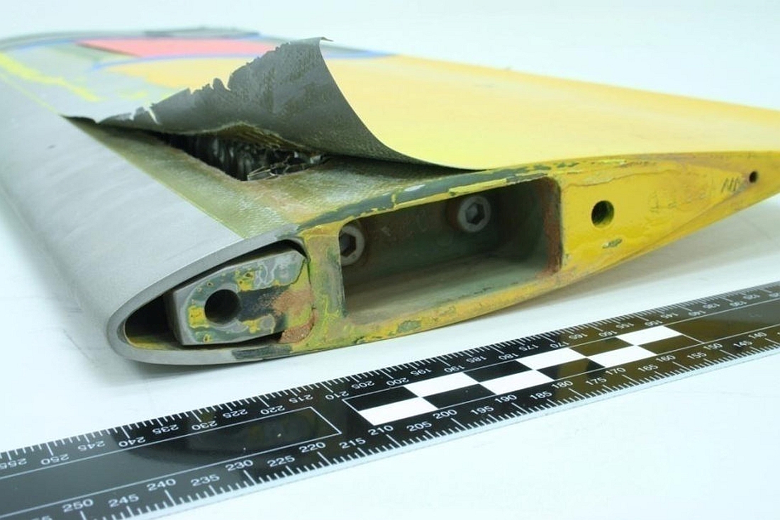
The main rotor blades mounted on C-FJLH at the time of the accident had been manufactured by the Robinson Helicopter Company (RHC) and bore part number C016-2. They consisted primarily of an aluminum alloy honeycomb core structure, bordered along the front by a stainless steel spar forming the leading edge and a trailing edge doubler in the back. A stainless steel skin covered the components above (upper skin) and below (lower skin) the blade, and was bonded to the trailing edge doubler, the honeycomb core structure and the spar (Figure 2).

These blades had a known tendency to debondFootnote 6 at the adhesive bond joint between the skin and the spar at the tip of the blade. Skin debonding can occur when the adhesive bond joint becomes exposed as a result of the top coat eroding or when corrosion appears below the internal aluminum tip cap. A blade is not considered airworthy if debonding, including microperforation, is detected along the bond joint.Footnote 7
In 2008, the U.S. National Transportation Safety Board (NTSB) issued 5 recommendationsFootnote 8 after 10 cases of debonding at the bond joint were discovered during maintenance inspections and visits between July 2006 and January 2007, and 4 cases of debonding occurred in flight in 2006 and 2007. These cases of debonding occurred far before the blades had reached their useful life of 2200 flight hours or 12 years, whichever came first. In its report, the NTSB expressed its concerns about the absence of long-term durability testing for blade certification and the lack of reliability and effectiveness of the non-destructive blade inspection technique recommended by RHC to detect bond flaws.Footnote 9
All of the known cases of debonding at the bond joints only affected the blade tip and, in the most serious cases, resulted in sudden separation due to peeling of the blade skin in flight (Figure 3).
1.6.1.1 Bonding technique
When the blades are manufactured, the upper skin and lower skin are overlaid at the bond joints along the spar, the trailing edge doubler and the tip cap, and held in place with a sprayed adhesive. The honeycomb core structure is also bonded to the trailing edge of the spar with the adhesive to ensure the solidity of the rotor blade (Figure 4).

Since it is impossible to know the cohesive quality of an adhesive before a blade is assembled, the manufacturer exposed a few blades assembled from the same batch of adhesive to high stresses, to the point of failure, to determine the ratio of the number of cohesive failuresFootnote 10 to the number of adhesive failures,Footnote 11 expressed as a percentage. Testing had to produce a result of at least 80% cohesive failures, otherwise the batch of adhesive and any blades assembled with it were destroyed.
A non-destructive inspection of the bond joints was also performed on the critical and non-critical parts of the blades once they were assembled. This inspection, commonly referred to as a tap test, consists of gently tapping the skin with a small hammer designed for this purpose, or a specific coin,Footnote 12 and listening to the sound produced by the tapping. A change in sound may indicate an adhesive failure, among other things. The tap test is also used during maintenance inspections, and to date, it is the only non-destructive inspection technique recommended by RHC for detecting bond flaws.
1.6.2 Airworthiness Directive
An AD is an instruction issued by a regulatory authority, such as Transport Canada Civil Aviation (TCCA), the U.S. Federal Aviation Administration (FAA) and the European Union Aviation Safety Agency (EASA) in Europe, after discovering a problem that compromises flight safety and requires mandatory maintenance and/or operational action as a corrective and/or preventive measure. In Canada, regulations recognize the mandatory status of foreign ADs and equivalent notices issued by a foreign civil aviation authority having jurisdiction over the type design of the aeronautical product.Footnote 13
Taking off in an aircraft that does not meet the requirements of an AD is a violation of the CARs. Action taken to meet the requirements of an AD should be documented in the appropriate technical recordsFootnote 14 and certified with a maintenance release, if needed.Footnote 15
In response to the recommendations issued by the NTSB in 2008, the FAA issued AD 2011-12-10, which came into effect on 05 July 2011, and was replaced by AD 2014-23-16 on 09 January 2015.
AD 2014-23-16 included the following mandatory actions:
- Before the first flight each day, the joint had to be visually checked for any exposed metal surface between the skin and the spar on the lower surface of each blade (Figure 5). The visual inspection could be performed by someone who had at least a private pilot licence and it had to be entered into the aircraft records.
- If there is any exposed metal surface at the joint, an inspection should be conducted by an aircraft maintenance engineer (AME) in accordance with Service Bulletin SB72, issued by RHC, before each flight.
- Regardless of their condition, all blades had to be taken out of service and replaced with blades bearing a different part number, depending on the helicopter model, by 09 January 2020.
![Area of the lower skin on a blade to visually inspect (Source: Robinson Helicopter Company website [https://robinsonheli.com/] for the helicopter and TSB for the blade and annotations)](/sites/default/files/eng/rapports-reports/aviation/2019/a19q0109/images/a19q0109-figure-05.jpg)
In response to the NTSB recommendations, RHC issued Service Bulletin SB72 on 30 April 2010. This bulletin indicated, among other things, that the blades needed to be inspected by an AME at a maximum interval of 100 hours of time-in-service or during every annual inspection, whichever came first. SB72 was revised (Revision A) on 19 July 2012. This revision reduced the interval between inspections to 4 months. It should be noted that SB72 and Revision A both indicated that the tap test should be used to inspect the blades.
In Canada, when a service bulletin is issued by a foreign manufacturer, such as RHC, and the bulletin is incorporated by reference in an AD that applies to the aircraft in question, compliance is mandatory.Footnote 16
With regard to this occurrence, SB72 was incorporated by reference in AD 2014-23-16, making its application mandatory. However, given that SB72 Revision A was only referred to as an alternate means of compliance with the AD, compliance was not mandatory, and neither was the blade inspection by an AME every 4 months.
Examination of the journey log revealed that application of AD 2014-23-16 was entered only during the 4 annual inspections performed after the aircraft was purchased in 2015. The most recent inspection was dated 03 April 2019, and no flaws were reported. Between 03 April and 04 July, the date of the last entry in the journey log, 19.6 hours were logged and no anomaly was noted.
Information gathered during the investigation indicated that the pilot was aware of the AD and its requirements, but there was no indication that the blades were being visually inspected before the first flight each day.
1.7 Weather information
The weather station closest to the accident site was in Saint-Michel-des-Saints, Quebec. Located approximately 40 km to the north-northeast, it indicated the following conditions at 1300:
- temperature 28°C;
- dew point 15°C;
- winds 120° true (T) at 2 knots.
The “Clouds and Weather” graphic area forecast issued at 0731, and valid from 0800 to 1400 on 10 July, indicated scattered clouds with an expected base at 8000 feet above sea level and visibility greater than 6 statute miles.
There was no indication that weather was a factor in this occurrence.
1.8 Aids to navigation
The pilot had a portable Garmin Aera 796 global positioning system (GPS) mounted on the instrument panel with a bracket. The GPS was used as an aid to navigation. It was recovered and analyzed by specialists at the TSB Engineering Laboratory. The GPS’ internal memory did not have any information on the occurrence flight because the flight recording function was not activated.
1.9 Communications
No distress or any other messages from C-FJLH were heard and reported.
1.10 Aerodrome information
Not applicable.
1.11 Flight recorders
The aircraft was not equipped with a flight data recorder (FDR) or a cockpit voice recorder (CVR), nor was either required by regulation.
1.12 Wreckage and impact information
1.12.1 General
The aircraft was found in a vertical position on a rocky outcrop in a densely wooded area (Figure 6). The landing gear, the cabin roof, and the floor at the front of the cabin had collapsed. The windshield had shattered; the rear doors and the door on the pilot side had ejected, leaving only the passenger door still attached to its frame. The seat backs had collapsed backward and the seat cushions had sunk down. The front passenger safety belt, which included a lap belt and a shoulder harness, was found undone. There was fuel in both tanks.

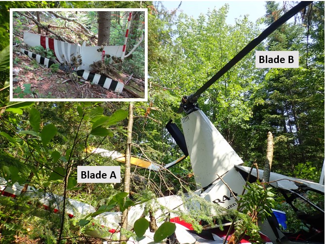
The main rotor mast and rotor head were still attached to the main gearbox. The main rotor drive belts were in good working order and the belt tensioning mechanism was in the taut position. The main rotor blades did not show signs of the damage that is typically sustained on impact when the blades are rotating. One of the blades (blade A) was bent in several locations while the other blade (blade B) was straight but fractured at the tip (Figure 7).
Although the tail boom was damaged, it was still attached to the fuselage, and the driveshaft was still attached to the upper pulley of the drive system. The tail rotor assembly and horizontal and vertical stabilizers were separated from the tail boom. They were found approximately 6 metres from the wreckage, at the foot of a tree. The tail rotor blades did not show signs of significant damage.
Pieces of small branches covered the wreckage and the immediate area when the first responders arrived at the scene. The pilot’s body was found inside the aircraft, in the pilot seat, with the seat belt fastened, while the passenger’s body was found approximately 66 metres away. The aircraft debris was scattered within a short distance of the wreckage. TSB investigators found no trace on the ground or any other clues that could indicate the aircraft’s longitudinal or lateral speed at the time of impact. Only the tree tops in the area above the wreckage showed signs of impact.
The wreckage was transported to the TSB Engineering Laboratory for detailed examination.
1.12.2 Examination of the wreckage
The fuel found in the tanks was uncontaminated AVGAS 100LL. The buckle on the front passenger’s safety harness was working properly and did not show signs of major damage. An examination of the damage to the aircraft combined with information about the passenger’s weight enabled investigators to estimate that the force of deceleration experienced by the passenger was between 17 G and 36 G.Footnote 17 The force of deceleration experienced by the pilot could not be estimated; however, given that he was heavier than the passenger, it would have been much higher, giving him little chance for survival.
The engine did not show typical signs that it was running at the time of impact. After a more detailed examination, there were no signs of mechanical failure or deficiency in the engine before the impact.
1.12.3 Damage to main rotor blades
If a helicopter descends through trees while the main rotor is not turning, it is likely that the blades will undergo excessive upward bending from the pressure of the branches. This excessive bending causes deformations by compression of the upper skin only, meaning the upper side of the blade. The lower skin should show signs of scratches, nicks or dents from contact with branches (Figure 8).

An initial examination of the blades enabled investigators to identify deformations in the upper and lower skins, complete and partial fracture lines, and signs of impact with tree branches on the lower skin. The spar leading edges did not show signs of damage consistent with a blade in rotation when it came into contact with the trees.
1.12.3.1 Examination of blade A
The numerous deformations across the skin on both sides of the blade suggest that the skin was subject to compression several times in flight. The deformations are consistent with damage created by excessive upward and downward bending of the entire blade. This flapping motion generally occurs when the centrifugal force that helps to keep the blades flat is reduced due to the blades’ lower rotation speed.
No signs of perforations or dents were found in the lower skin, indicating that there was no significant interaction between the blade and the branches during the descent.
1.12.3.2 Examination of blade B
The blade was broken approximately 38 inches from the tip (station RS161). It had several fracture lines and many deformations in the upper and lower skin, consistent with excessive upward and downward bending motion and torsion. The examination showed that the deformations caused by excessive torsion likely occurred before those caused by excessive bending.
Close visual observation revealed that the metal surface of the joint was visible in a few locations along the spar near station RS161. Signs of debonding and gaps in the skin at the spar bonding joint were also noted. Although the lower skin had debonded from the spar after fracturing, the enlargement of these areas shows that air had caused the paint and its underlying layer to erode over time, and that the erosion was not the result of paint suddenly chipping as the skin separated at the spar bonding joint (Figure 9). It is likely that the metal surfaces in these areas would have been visible and detectable before takeoff of the occurrence flight in optimal observation conditions allowing such details to be seen. The visual pre-flight inspection should be done in adequate lighting and at a suitable distance for signs of debonding to be identified, which may require equipment such as a stepladder and a flashlight.

The presence of sap and traces of the impact on the lower skin indicate that the blade came into contact with small branches as the helicopter descended through the trees. Also, an examination of the marks left by these contacts revealed that the deformations caused by the torsion and bending motions happened before the blade came into contact with the branches; in other words, they occurred during flight.
It was established that the torsion increased progressively, which likely caused vibrations in flight that increased in intensity until they became severe. If this torsion appears in flight, it can significantly affect the blade’s aerodynamic performance and the aircraft’s manoeuvrability.
1.12.3.3 Adhesive failure at the bond joints
A destructive inspection of the blade was performed to confirm the observed debonding of the skin. Separation of upper and lower skin samples confirmed the presence of several adhesive failures, of variable sizes, between stations RS132 and RS165 (Figure 10).

The examination revealed that, in some areas, debonding of the skin had allowed humidity to infiltrate below the skin and weaken the adhesion to the bonding joint over time.
In addition to the adhesive failures, there were several places where the adhesive on the surface between the honeycomb core structure and the trailing edge of the spar did not have the usual imprints found when there is contact between them. This was true over a cumulative length of 20 inches (yellow area), indicating that the condition had been present since the blade was assembled and was the result of a manufacturing defect.
1.13 Medical and pathological information
There was no indication that the pilot’s performance was affected by medical, pathological, or physiological factors.
1.14 Fire
There was no post-impact fire.
1.15 Survival aspects
Filing a flight plan is a reliable and effective method to ensure that an overdue aircraft is reported. Also, regulations in effect at the time of the occurrence required that pilots file either a flight plan or a flight itinerary,Footnote 18 which was not done in this case.
It is important to occupant survival that search and rescue teams are notified quickly of any delays. After an accident, the life expectancy of an injured survivor may drop by up to 80% during the first 24 hours, and the life expectancy of an uninjured survivor may drop rapidly after the first 3 days.Footnote 19 In this occurrence, the disappearance was reported approximately 23 hours after the estimated time of the accident.
1.15.1 Emergency locator transmitter
The aircraft was equipped with a Kannad emergency locator transmitter (ELT), model 406 AF-compact, which transmitted on frequencies 121.5 MHz and 406 MHz. The ELT bracket was mounted in the compartment where the main gearbox was located.
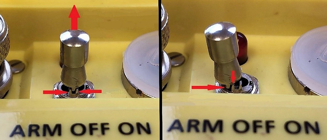
The ELT has a 3-position toggle switch: OFF (centre), which means that the ELT is turned off completely; ARM (left) which means that the ELT is turned on and ready to activate on impact; and ON (right), which allows the pilot to manually activate the ELT and transmit a distress signal directly (Figure 11).
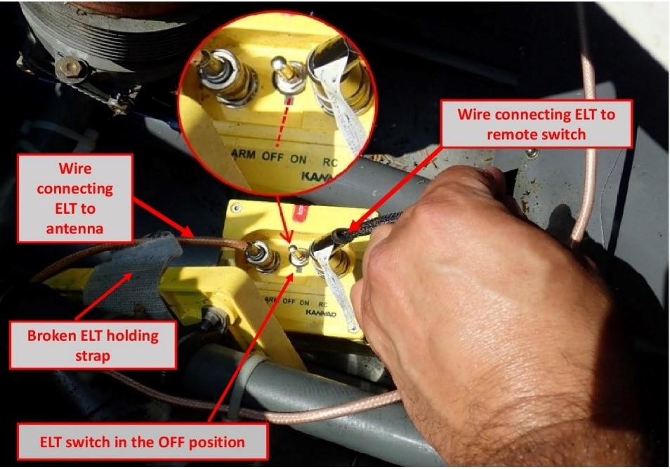
The ELT was not accessible from inside the cabin, but it could be activated by the switch on the remote control panel located between the pilot’s seat and the front passenger’s seat. The 3 positions on the switch are ON, ARMED and RESET/TEST. The switch cannot be kept at the RESET/TEST position, and once it is released, it automatically returns to the ARMED position. Like the ELT switch, the remote switch has a locking system that prevents it from being accidentally moved from the ARMED position to the ON position. It should be noted that the remote switch has no effect on the ELT if the ELT switch is set to the OFF position and that the remote control panel does not indicate the ELT switch position.
Upon initial examination of the wreckage at the accident site, the ELT did not appear to be damaged. Although it was no longer in its mounting bracket because the holding strap had broken, the ELT was still attached to the antenna by its wire. The antenna and wire showed no apparent signs of significant damage. The ELT switch was found in the OFF position and the switch on the remote control panel was found in the ON position (Figure 12).
The ELT and its components were sent to the TSB Engineering Laboratory, where tests revealed that it was in good working order, it complied with the manufacturer’s technical parameters, its battery was at full capacity, its antenna was in good working order and a distress signal would have been transmitted on impact if the switch had been in the ARM position.
The examination of the switch on the remote control panel indicated that it was working properly and the locking system did not show any signs of deficiency. It is therefore unlikely that this switch was moved to the ON position by an unsecured object inside the cabin at the time of impact.
Furthermore, the electrical wire that connected the ELT to the remote control panel was severed by the lower left corner of the auxiliary fuel tank, which collapsed at the time of impact.
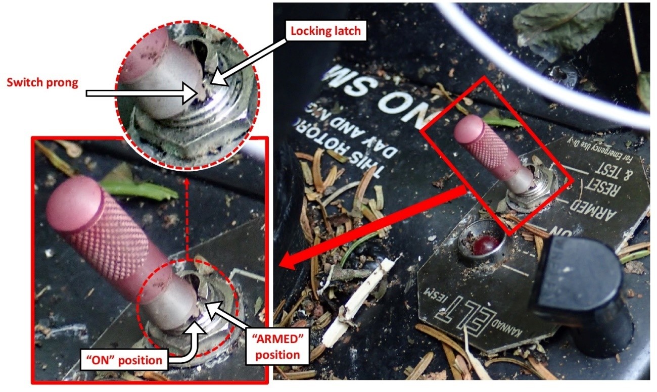
1.15.1.1 Emergency locator transmitter switch locking system
An ELT with a switch that has an OFF position must be equipped with a locking system to prevent the switch from accidentally moving to the OFF position during an impact.
The locking system of the occurrence ELT model was designed such that a prong, aligned with the centre of the switch, is blocked by a locking latch on either side to prevent it from moving from one position to another. To move the switch, it must be pulled up to disengage the switch prong from the latches and set it to the desired position (Figure 13).
A more thorough examination of the occurrence ELT revealed that the locking latches between the OFF position and the ARM position were broken (figures 14 and 15). Furthermore, the examination showed that the fracture surface of these latches was smooth, indicating that the switch had moved several times between the OFF position and the ARM position over time.


Impact testing on the ELT showed that the switch could move to the OFF position under a minimum impact force of 1.8 G. The investigation was unable to determine whether the switch was in the OFF position before impact or if it moved to this position on impact.
1.15.1.2 Periodic inspections of emergency locator transmitters
Orolia, the manufacturer of Kannad ELTs, indicates in its user manual that a pilot or AME must perform regular operational tests (self-test) on the ELT to identify any defects. It also recommends performing the self-test once a month, but not more than once a week, as the test can weaken the battery if it is performed too often.Footnote 20 There was no indication in the aircraft journey log that self-tests had been performed other than during annual maintenance inspections. The CARs consider the manufacturer’s self-test requirement to be a recommendation rather than an obligation in Canada.
Furthermore, ELT maintenance by an AME was required by Transport Canada (TC) but not by the manufacturer. However, the manufacturer issued Service Letter SL S1840501-25-05Footnote 21 Guidelines for periodic inspections as a reference guide for the maintenance of some of its ELTs, including the occurrence ELT. The maintenance interval applicable in this case was not to exceed 12 months according to the standardFootnote 22 in effect at the time of the accident. Also, CARs Standard 571, Appendix G, detailed what needed to be inspected.
The aircraft’s journey log indicated that ELT recertification was completed on 03 April 2019 in accordance with CARs Standard 571, Appendix G, and the manufacturer’s Service Letter SL S1840501-25-05. The steps outlined in these documents did not help to identify the defect in the switch’s locking system. Once the ELT was recertified, it was sent to the AMO that was tasked with reinstalling it on its mounting bracket in the helicopter. The strap on the ELT mounting bracket showed signs of advanced wear and should have been replaced according to the ELT’s manufacturer’s recommendations. The AMO performed a self-test using the switch on the remote control panel once the ELT was reinstalled on its mounting bracket and confirmed that it was serviceable.
1.15.2 Organization of the search
In Canada, search and rescue operations are a shared responsibility between the CAF and the CCG. The area of responsibility for search and rescue operations is divided into 3 regions: Victoria, Trenton and Halifax.
In this occurrence, the JRCC Trenton was responsible for coordinating the search until 21 July 2019, at which point it ceased its operation and transferred the responsibility for search and rescue to the SQ.
1.15.2.1 Resources
Search operations began on 11 July. On the afternoon of 12 July, just over 24 hours after the search began, the operation level was escalated to “major”. This escalation allowed the JRCC to increase its material and human resources (Table 4 and Table 5) and create a unit independent of the control centre to focus exclusively on this incident.
| Search organization | Aircraft type (number) |
|---|---|
| Canadian Armed Forces | Airplane (3), helicopter (4) |
| CASARA*/SERABEC** | Airplane (9) |
| Canadian Coast Guard | Helicopter (1) |
| Sûreté du Québec | Helicopter (1) |
| Total*** | Airplane (12), helicopter (6) |
* The Ontario Civil Air Search and Rescue Association is a national volunteer organization funded by the Department of National Defence to assist the Royal Canadian Air Force in their mandate of providing air search and rescue in Canada. (Source: http://www.casaraottawa.org/)
** “Sauvetage et recherche aériens du Québec” is a group of volunteers dedicated to promoting aviation safety. It provides air support to Canada’s National Search and Rescue Program. (Source: https://www.serabec.ca/a-propos)
*** 447.5 flight hours were conducted, excluding those conducted by the CCG and SQ.
| Human resources | Number of people | Total number of hours |
|---|---|---|
| Observers | 44 | 347 |
| Other* | Approximately 77 | Not available |
* Including administrative, logistics and media relations staff.
The search was coordinated from the JRCC’s secondary facilities in Belleville, Ontario, and air operations were managed from the air task force command centre temporarily established in Mirabel, Quebec.
Also, several aircraft ownersFootnote 23 and individuals wanting to help participated in the search efforts and their dedication is noteworthy. However, these volunteers could not be included on official air search teams and were not authorized to fly over the search areas defined by the JRCC for safety reasons. However, CAF established and maintained communications with these volunteers to advise them daily of the areas reserved for official operations, which enabled them to participate by flying over other areas without coming into conflict with the aircraft under the JRCC’s responsibility.
1.15.2.2 Search tools
In the event of an aircraft accident, the fastest means to notify search and rescue teams of the incident is the transmission of an ELT distress signal on frequency 406 MHzFootnote 24 and its receipt by the Canadian Mission Control Centre (CMCC).
If there is no distress signal, when a flight plan is filed verbally or online with an FSS, a search will automatically be initiated 1 hour after an aircraft’s expected time of arrival unless the pilot has indicated otherwise, if the pilot does not close the flight plan. Alternatively, a flight itinerary filed with a responsible personFootnote 25 also triggers a search with a minimum delay after the expected time of arrival. Also, the flight plan and flight itinerary provide useful information for search purposes, including the planned flight route, the amount of fuel on board and the number of people on board. This information is important because it enables search and rescue teams to focus their efforts along the planned flight route and minimize the time necessary to find the aircraft and its occupants.
If there is no distress signal, and no flight plan or flight itinerary, search operations may not be started within a reasonable timeframe, greatly reducing the occupants’ chances of survival. Also, the lack of information regarding the flight path taken by the missing aircraft will increase the search area and the time necessary to find the aircraft, while reducing the occupants’ chances of survival.
In this occurrence, the uncertainty regarding the time of departure, planned flight route and amount of fuel remaining on board led to several hypotheses as to the areas where the aircraft could have been located at the time of the accident. This resulted in expanding the initial search area.
A similar case involving a Robinson 66 helicopter occurred on 04 March 2019.Footnote 26 Its disappearance was reported to the authorities over 30 hours after the accident. The absence of a flight plan or flight itinerary and the fact that the ELT switch was also found in the OFF position prevented the search from being initiated within a reasonable timeframe and the aircraft from being located quickly. The aircraft was found on 11 March, 7 days after the accident, and there were no survivors.
In this type of situation, where there is limited information about the flight, the JRCC must use all sources of information that can help reduce the extent and length of the search. Time and resources are needed to gather this information, with no guarantee that the information obtained will lead to the missing aircraft being found rapidly.
In this occurrence, several sources of information were analyzed, including:
- satellite images;
- data from civil and military radars;
- radio communications;
- aircraft history and pilot’s flying habits;
- data from surveillance and detection equipment on board the CP140 Aurora;
- results of the portable cellphone signal detector;Footnote 27
- historical data from occupants’ cellphones.
Only the analysis of historical data from occupants’ cellphones and the use of this data for triangulation purposes helped to reduce the search area and locate the aircraft.
1.15.2.3 Cellphone network
A cellphone network consists primarily of antennas and central offices that relay calls automatically. When a person uses their cellphone to make a call or send a text message, the closest antenna captures the cellphone transmission and sends it to a central office. The central office locates the phone of the person receiving the call using their number and relays the call through the nearest antenna if the call is made to a cellphone, or through a landline if the call is made to a landline.
Network coverage depends on the number of antennas and their locations. In urban areas, where population is dense, many antennas are installed on top of buildings. Since several antennas are located close to each other, they have a limited range. In less populated areas, there are a lot fewer antennas, which means that they must be installed on high towers and their range must be broader to provide services over a wider range.
A person who uses their cellphone while moving does not lose communication because the central office detects the movement as the cellphone signal connects to various antennas along the way. If the phone conversation or text message exchange ends, the central office stops recording conversation data.
The central offices record and retain for a limited period various data related to cellphone connection to the network. The data retention period varies depending on the type of data; for example, data on the location of the antennas to which the cellphone connected or data on the angle of the signal captured by an antenna. Once this period ends, the data are automatically erased from the central office.
In this occurrence, data on the location of the antennas that captured the occupants’ cellphones was retained for a period of 14 months, while the data on the angle of the signals captured was only retained for 7 days.
The telephone service provider was aware that historical data could be lost if a request for the data was submitted after the data retention period was over. The service provider therefore made a backup of all historical data pertaining to the cellphones of the 2 occupants before the data was erased. When the service provider received an official request to communicate this data, it was able to provide all data, even though the request was received 8 days after the accident and the retention period for some of the data was over.
1.15.2.4 Locating a cellphone
There are 3 main tools for locating a cellphone with more or less precision:
- the GPS function built into the cellphone, if it is a smartphone;
- a portable cellphone signal detector;
- the triangulation calculated using historical data.
In the case of an emergency, the telephone service provider may, at the request of emergency services, remotely query a telephone’s built-in GPS to pinpoint its exact position in real time, with no delay.Footnote 28 To be successful, the phone must be turned on and working properly; it must capture satellite signals and be connected to a cellular network. If the cellphone is not working properly because it is broken or the battery is dead, real-time location detection is impossible.
It is also possible to locate a cellphone using a portable detector that picks up the waves transmitted by the telephone within a given radius. To be successful, the telephone must be turned on and working properly, but it does not need to be connected to a cellular network. It should be noted that CAF aircraft do not have this equipment.
Finally, triangulation from historical data does not help to locate a cellphone, but rather to determine the area or location where the phone last connected to a cellular network. This historical data, which is retained by the cellular service provider, can be shared with an applicant who has a court order given that the request pertains to protected personal information. It should be noted that the JRCC does not have the necessary authority to obtain such a court order, and therefore cannot access this information.
In this occurrence, 9 attempts were made to locate the occupants’ cellphones using their GPS function, between the 1st and 4th day of search operations, all unsuccessful. A portable cell signal detector was used by the SQ on the 9th day of the search, without success. The service provider received a court order on 18 July, 8 days after the accident, to hand over historical data from the occupants’ cellphones to police authorities. The information was passed on to police authorities the next day, even though the provider had been given 30 days to share this information.
1.15.2.5 Search areas
When an aircraft is reported missing and only the point of departure and final destination are known, efforts must be made to determine the potential locations where the aircraft may have flown in addition to considering a straight path to the final destination. Knowing the amount of fuel on board helps to restrict the search perimeter based on the remaining flight endurance and the aircraft’s cruising speed. Generally, an airplane flies further than a helicopter because it is faster and more likely to be detected by radar because it flies higher. Helicopters usually fly below radar coverage and do not depend on specific facilities to land, which can complicate search operations.
In this occurrence, the pilot had other properties that were considered as possible alternate destinations other than Sainte-Sophie. The information received prompted the JRCC to extend the initial air search area to the north and northwest of Lac de la Bidière. This initial area corresponded to a surface area of approximately 26 750 square kilometres (Figure 16).

The JRCC also had to deal with elements beyond its control. The flight endurance of Griffon helicopters, limited to approximately 2.5 hours, prevented their use in areas too far from refuelling locations. A Cormorant helicopter, with a fuel endurance of approximately 5 flight hours, was asked to join the search operations on the 4th day. Poor weather conditions also caused several delays in the search. Finally, the high density of the forest considerably deterred efforts, preventing observers from seeing clearly below the tree line, forcing a reduction in the distance between the tracks flown and increasing the time necessary to conduct the search flights.
On 13 July, when the JRCC was certain that the helicopter had taken off southbound, the search area could be reduced to 11 320 square kilometres. On 16 July, it was possible to reduce the search area to 3600 square kilometres as a result of the first triangulation calculations; the search area continued to be reduced gradually until it was 2058 square kilometres. With no new information to process, and having flown over all areas more than once, including the location where the aircraft was found, the JRCC ceased its search operations on 21 July 2019. Responsibility for the search was transferred to the SQ.
Triangulation calculations continued when more precise data was obtained, until a triangulation point obtained on 24 July enabled search teams on the ground to find the aircraft the next day.Footnote 29
1.16 Tests and research
1.16.1 TSB laboratory reports
The TSB completed the following laboratory reports in support of this investigation:
- LP167/2019 – ELT Analysis
- LP181/2019 – NVM Recovery GPS and PEDs
- LP183/2019 – Fuel Inspection
- LP184/2019 – Passenger Seatbelt Examination
- LP186/2019 – Warning Lamp Analysis
- LP187/2019 – Aircraft Instrument Analysis
- LP188/2019 – Aircraft Radio – Transponder Analysis
- LP195/2019 – MRB Examination and Failure Analysis
- LP267/2019 – Engine Examination
- LP083/2020 – Impact Force Estimation
1.17 Organizational and management information
Not applicable.
1.18 Additional information
Not applicable.
1.19 Useful or effective investigation techniques
Not applicable.
2.0 Analysis
2.1 General
The pilot was certified and qualified to conduct this flight. However, his medical certificate had expired in October 2018, which meant that he could no longer exercise the privileges of his licence and ratings. Nevertheless, there was no indication that fatigue or any other medical, pathological or physiological factors affected the pilot’s performance.
Weather conditions were favourable for a visual flight rules (VFR) flight, clean fuel of the appropriate type was found in the tanks, and examination of the engine and its components did not reveal any anomalies that could have contributed to the occurrence.
Therefore, the analysis will focus on the following elements:
- main rotor blade failure in flight;
- blade inspection;
- occupant survival; and
- search operation.
2.2 Main rotor blade failure
The initial examination of the accident site and wreckage, and the examination of the main rotor blades, revealed that the descent path was almost vertical and that the blades were barely rotating when the aircraft fell through the trees. This indicates that the blade rotational speed during the flight dropped to a level low enough to prevent the aircraft from remaining in flight and the pilot from being able to conduct a controlled landing.
A thorough inspection of the deformations in the blades’ skin revealed that they were the result of excessive torsion and bending movements that had occurred in flight, and that the torsional deformations probably appeared before the bending deformations.
A torsional deformation is the result of a loss of the structural stiffness of a blade. If a blade loses stiffness during flight, the blade profile cannot remain intact due to the constraints and forces being applied to it, and it distorts. Deformation of the profile creates an imbalance between the 2 blades, which can produce excessive flapping, causing bending deformations on the skin, as seen on each of the blades. Such a situation can rapidly cause a loss of control of the aircraft and potentially lead to an in-flight breakup.
During the examination, one of the blades was found to have multiple adhesive failures in the same section, unrelated to the impact with the trees during descent.
These failures resulted in the breakup of certain sections of the joint between the lower skin and the spar, causing humidity to infiltrate below the skin, which weakened the adhesive bond joint over time.
Also, the blade examination showed a lack of imprints in the adhesive applied between the trailing edge of the spar and the honeycomb core structure over a cumulative length of 20 inches. This indicates that this area had never bonded and that this manufacturing defect had existed since the blade was initially assembled.
Finding as to causes and contributing factors
It is likely that the adhesive failures that appeared gradually over time and a pre-existing manufacturing defect contributed to significantly reducing the stiffness of one of the blades, which caused strong vibrations during the occurrence flight.
A pilot faced with significant vibrations will tend to want to manoeuvre for a landing as quickly as possible. Given that the examination of the engine did not show any mechanical defects or malfunctions, or typical signs that it was running at the time of impact, it is possible that the pilot cut the engine to try to reduce the intensity of the vibrations.
Finding as to causes and contributing factors
At a certain point, the rotational speed of the main rotor fell too low, preventing the aircraft from remaining in flight. This was followed by a vertical drop and impact with the ground.
2.3 Blade inspection
The model of the blade in this occurrence had a useful life of 2200 hours or 12 years, whichever came first. However, this model was known to be prone to bond failures well before the end of its useful life. In this occurrence, the blades had accumulated approximately 770 flight hours in 10 years.
To ensure the aircraft’s airworthiness, the requirements stated in Airworthiness Directive (AD) 2014-23-16 needed to be applied by the pilot of the occurrence aircraft from the time it was purchased in 2015 until the mandatory removal from service date for the blade, which was 09 January 2020. The AD required, among other things, that an inspection be performed by an aircraft maintenance engineer at a maximum interval of 100 hours of time-in-service or during every annual inspection, and that a visual inspection be performed before the first flight of the day by someone who was at least a qualified pilot.
2.3.1 Maintenance
Although the pilot was not having the blades inspected by an AME every 4 months, as recommended by the Robinson Helicopter Company (RHC), and he was not obliged to do so, the last blade inspection was dated 03 April 2019, less than 4 months before the accident. The inspection was conducted in accordance with Revision A of Service Bulletin SB72 and no defects were noted at the time.
The inspection method used was the tap test. Although a tap test can help identify bond flaws, its reliability depends on the degree of experience of the AME carrying out the test and the conditions under which it is performed, among other things. For example, if an AME does not perform this test on a regular basis or carries out the test in a noisy environment, the more subtle differences in sound caused by smaller bond flaws may be difficult to perceive. While a detected change in sound automatically results in the blade being taken out of service, a failure to perceive a change in sound does not guarantee the absence of bond flaws.
The thorough examination of the adhesive failures showed that the failures had not appeared suddenly, but rather had appeared gradually over time.
Finding as to causes and contributing factors
It is likely that when the last inspection was performed in April 2019, the adhesive failures were already present and went undetected by the tap test.
2.3.2 Pre-flight
Before the first flight each day, the lower skin of the blades needed to be visually inspected to detect any exposed metal surface at the skin-to-spar bonding joint, as required in AD 2014-23-16. It was also necessary to perform and record the action in the journey log to maintain the validity of the aircraft’s airworthiness certificate. If the visual inspection revealed significant erosion of the paint, exposing metal surface, the blade had to be inspected by an AME before the flight. If the AME noted debonding or tiny holes, the blade needed to be taken out of service immediately.
The TSB’s examination of the blades revealed that exposed metal surfaces at the skin-to-spar bonding joint on one of the blades would have been visible and detectable before takeoff of the occurrence flight in optimal observation conditions allowing such details to be seen.
The investigation was not able to determine if the pilot had identified this condition before the flight. However, various lighting conditions and a lack of equipment such as a stepladder can make the visual inspection of the blades less effective because of their height. For example, visually inspecting the blades while they are backlit can make it more difficult to detect small surfaces of exposed metal and they may go undetected.
The investigation determined that the pilot was aware of the AD and its requirements. However, contrary to the AD instructions, the mandatory visual inspections were never recorded in the aircraft’s journey log after it was purchased in 2015, which invalidated the aircraft’s airworthiness certificate. Although the absence of entries in the journey log does not mean that the visual inspection was not being done, based on the information gathered, the investigation was unable to confirm compliance with the AD.
2.4 Occupant survival
When the first responders arrived, the pilot’s body was inside the aircraft while the passenger’s body was 66 metres away. The information gathered during the investigation led investigators to believe that only the passenger survived a certain period of time after the initial impact. The force of deceleration experienced by the passenger, assessed based on the damage to the aircraft and the passenger’s weight, was estimated to be between 17 G and 36 G. The typical tolerance level for the human body, established to be between 20 G and 25 G for vertical deceleration, falls within this range.
Finding: Other
Consequently, the impact allowed for the possibility of the passenger surviving.
This raises questions as to other factors that may have influenced the passenger’s chances of survival in this occurrence.
In any situation where a person is injured, their chances of survival may depend how quickly they receive care. In many cases where there is a dense population, emergency services are quickly notified by one or more witnesses via cellphones, which are very common today. In these cases, the response time depends primarily on the time it takes for emergency crews to arrive on the scene of the accident.
When an aircraft crashes in an uninhabited area, it is unlikely that a bystander will witness or become aware of the accident and notify emergency services. Other means are therefore necessary, such as an emergency locator transmitter (ELT), to notify emergency services, particularly when the injured persons are unable to call for help.
2.4.1 Emergency locator transmitter
Finding: Other
The ELT switch was found in the OFF position and the remote ELT switch was found in the ON position.
The examination of the remote switch did not reveal that it was broken or malfunctioning. To move the switch lever to the ON position, the lever must first be pulled up. It is therefore unlikely that an unsecured object would have moved it to the ON position upon impact. It is possible that one of the occupants moved the lever of the remote switch to the ON position. However, this action did not activate the ELT, because the ELT switch itself was in the OFF position and the wire that connects the remote switch to the ELT was severed.
The investigation was unable to determine whether the ELT switch was in the ARM position before impact. However, less than 4 months before the accident, the ELT was reinstalled in the aircraft after recertification, and it passed an operational test, indicating that the switch was in the ARM position at that time. There were no subsequent entries in the journey log indicating that self-tests were performed on the ELT regularly, as recommended by the manufacturer. This test would have helped to detect the incorrect position of the switch if it had been moved to the OFF position during the period between recertification and the accident.
The tests performed on the occurrence ELT determined that the locking latches for the ELT switch, between the OFF position and ARM position, had been broken for some time, allowing the switch to move freely between the 2 positions under a minimum force of 1.8 G. Knowing that the switch was in the ARM position less than 4 months before the accident, it is reasonable to believe that the switch moved to the OFF position at the time of the accident given that the force of the impact was well above the minimum force of 1.8 G.
The examination of the ELT showed that if the locking latches had been intact and the switch had been in the ARM position, the ELT would have transmitted a distress signal, which would have enabled search and rescue teams to find the aircraft quickly using locator information.
Finding as to risk
During an ELT maintenance inspection, if an anomaly is not detected or corrected, there is a risk that the ELT will not activate during an accident, which would delay search and rescue efforts and can reduce occupants’ chances of survival.
2.4.2 Flight plan or flight itinerary
Although existing regulations required the filing of either a flight plan or a flight itinerary, filing a flight plan is the most reliable method of reducing the time necessary to initiate a search if there is no distress signal. In this occurrence, no flight plan or flight itinerary was filed; this caused a delay in initiating the search, which began 23 hours after the accident. This amount of time is long enough to have a non-negligible impact on the survival of an injured occupant, whose chances of survival drop close to 80% during the first 24 hours, according to studies on the subject.
The information in a flight plan and a flight itinerary is immediately available and quite useful to search teams, who can quickly and effectively begin a search when advised of an overdue aircraft. The lack of information available for the occurrence flight when the search was initiated contributed to the widening of the initial search area to 26 750 square kilometres and the increase in resources needed to cover such a large area. Combined with the lack of distress signal, the fact that no flight plan or flight itinerary was filed likely had an impact on the chances of survival.
Finding as to risk
If no flight plan or flight itinerary is filed, there is a risk that a search will not be initiated within a reasonable timeframe, especially if no ELT signal is detected, which reduces the occupants’ chances of survival and deprives search and rescue teams of important information needed for the search.
2.5 Search operation
The search mobilized 18 aircraft, 44 observers and 77 people on the ground during the 11 days of the Joint Rescue Coordination Centre (JRCC) operations. Even when well organized and with sufficient resources, any search operation may have constraints that could have an impact on the time necessary to find a missing aircraft.
In this occurrence, the major constraint that prevented the search team from locating the aircraft from the air, even though it flew over the accident site several times, was the dense forest. Also, the aircraft’s almost vertical descent through the trees did not leave a trail of broken branches or trees, which would have been an effective visual clue and may have helped to locate the aircraft faster.
The aircraft was only found through the historical data from the occupants’ cellphones, which helped to perform several triangulation calculations until a precise point was identified 193 m from the wreckage. However, although triangulation is a widely recognized method, many of the data used for triangulation calculations are privileged information that can only be obtained with a court order. The JRCC does not have the necessary authority to request a court order and therefore depends on police authorities.
Finding: Other
Consequently, the JRCC did not have access to all of the information that could help it locate the missing aircraft.
Finding: Other
Furthermore, the court order to obtain the historical data from the occupants’ cellphones was filed with the telephone service provider 8 days after the accident.
Normally, 8 days is longer than the initial retention period for certain data that are automatically erased from the system. In this occurrence, the service provider took the initiative to make a backup copy of all data before they were erased, which enabled it to provide all data once the court order was received.
Although triangulation helped to find the aircraft in this occurrence, this method does not locate a cellphone, but rather it identifies the location where the phone last connected to the cellular network. Furthermore, due to associated administrative delays and the time required to perform the calculations, triangulation is not the preferred method used to quickly locate a missing aircraft and increase the occupants’ chances of survival.
Locating a GPS-enabled smartphone in real time is the fastest and most effective method. However, to use this method, the cellphone must be turned on and working properly and must be able to connect to the cellular network and capture satellite signals. Although the JRCC asked the service provider to “ping” the telephones from the 1st day of the search, the phones could not connect to the cellular network because of the location of the accident site and therefore they could not be located.
Another method for locating a cellphone consists of using a portable cellular signal detector. Although the cellphone must be turned on, it is not necessary for the phone to be connected to the cellular network, or to capture a satellite signal, or even to be fully functional; it must only be able to transmit signals. This means that the time remaining until a phone loses its ability to transmit a signal will depend on the battery level and the effects of the phone being exposed to the elements, such as rain.
The Canadian Armed Forces aircraft used in the search and rescue operations are not equipped with cellular signal detectors; therefore, these detectors could not be used from the beginning of the search. Police authorities began using a cell signal detector after 9 days; this is a long delay given the average battery life of current cellphones and the unknown status and battery charge of the occupants’ cellphones. After an accident, it is important to use these detectors quickly because a cellphone’s ability to transmit a signal can weaken rapidly. The investigation did not assess whether earlier use of a cellular signal detector could have helped to locate the aircraft faster.
3.0 Findings
3.1 Findings as to causes and contributing factors
These are conditions, acts or safety deficiencies that were found to have caused or contributed to this occurrence.
- It is likely that the adhesive failures that appeared gradually over time and a pre-existing manufacturing defect contributed to significantly reducing the stiffness of one of the blades, which caused strong vibrations during the occurrence flight.
- The rotational speed of the main rotor fell too low, preventing the aircraft from remaining in flight. This was followed by a vertical drop and impact with the ground.
- It is likely that when the last inspection was performed in April 2019, the adhesive failures were already present and went undetected by the tap test.
3.2 Findings as to risk
These are conditions, unsafe acts or safety deficiencies that were found not to be a factor in this occurrence but could have adverse consequences in future occurrences.
- During an emergency locator transmitter maintenance inspection, if an anomaly is not detected or corrected, there is a risk that the emergency locator transmitter will not activate during an accident, which would delay search and rescue efforts and can reduce occupants’ chances of survival.
- If no flight plan or flight itinerary is filed, there is a risk that a search will not be initiated within a reasonable timeframe, especially if no emergency locator transmitter signal is detected, which reduces the occupants’ chances of survival and deprives search and rescue teams of important information needed for the search.
3.3 Other findings
These items could enhance safety, resolve an issue of controversy, or provide a data point for future safety studies.
- The impact allowed for the possibility of the passenger surviving.
- The emergency locator transmitter switch was found in the OFF position and the remote emergency locator transmitter switch was found in the ON position.
- The Joint Rescue Coordination Centre did not have access to all of the information that could help it locate the missing aircraft because this information was privileged.
- The court order to obtain the historical data from the occupants’ cellphones was filed with the telephone service provider after the data retention period had expired.
4.0 Safety action
4.1 Safety action taken
4.1.1 Transportation Safety Board of Canada
On 11 February 2020, the TSB issued Aviation Safety Advisory A19Q0109-D1-A1 requesting that Orolia, the manufacturer of Kannad emergency locator transmitters (ELTs), and Transport Canada (TC) revise ELT periodic inspection procedures so that a failure in the switch locking system can be detected and corrected in the future.
4.1.2 Orolia
In its response on 19 March 2020, Orolia mentioned the following corrective actions:
- In the documents containing switch operation instructions, a warning was added to clarify the instructions and avoid inappropriate manoeuvres that could result in breakage of the switch locking latches.
- In the documents designed for Kannad ELT maintenance, a visual inspection of the switch locking latches will be added.
- Service letters called “Periodic Inspection” regarding Kannad 406 ELTs and Compact and Integra ELTs were updated and made available to the public on the company’s website.
- As a preventive measure, other relevant documents were identified and will be updated within 6 months.
4.1.3 Transport Canada
On 01 August 2019, TC updated Standard 571, Appendix G, which addresses ELT maintenance. This update introduces a requirement to visually inspect ELTs.
In its response on 03 April 2020 to Aviation Safety Advisory A19Q0109-D1-A1 issued by the TSB on 11 February 2020, TC stated that Transport Canada, Civil Aviation, did not plan on making any further modifications to Parts V and VI of the Canadian Aviation Regulations (CARs) with regard to ELT inspections for the following reasons:
- Corrective action was taken by Orolia (see listed elements in the previous section).
- The European Union Aviation Safety Agency (EASA) in Europe does not plan on making arrangements given the low rate of failure for this switch model, recorded between the end of 2007 and 31 December 2019. Also, TC did not receive any service difficulty reports regarding this switch model.
- Advisory Circular No. 571-025 called “Maintenance of Emergency Locator Transmitters (ELTs)” contains guidelines to check the status of ELTs and is available to the public on TC’s website.
Civil Aviation Safety Alert (CASA) No. 2020-05 on ELT inspections was published by TC on 22 April 2020 after Aviation Safety Advisory A19Q0109-D1-A1 was issued by the TSB on 11 February 2020. The CASA addresses visual inspection of ELTs and focuses on directing attention to switches on ELTs.
This report concludes the Transportation Safety Board of Canada’s investigation into this occurrence. The Board authorized the release of this report on . It was first released on .
Correction
Further to comments received after publishing this report, the Board requested an independent review of the conclusions of Air Transportation Safety Investigation Report A19Q0109. Following a thorough evaluation of the review report, the Board has made the following changes to the investigation report:
In section 1.12.3.2 Examination of blade B:
- The sentence “It is highly likely that the metal surfaces in these areas were visible and detectable before takeoff of the occurrence flight.” was modified as follows: “It is likely that the metal surfaces in these areas would have been visible and detectable before takeoff of the occurrence flight in optimal observation conditions allowing such details to be seen.”
- Figure 9 was modified to highlight the visible metal surfaces by adding arrows along the affected spar.
- The sentences “It was established that the torsion increased progressively during the flight, which likely caused vibrations that increased in intensity until they became severe. This torsion significantly affected the blade’s aerodynamic performance and the aircraft’s manoeuvrability.” were modified as follows: “It was established that the torsion increased progressively, which likely caused vibrations in flight that increased in intensity until they became severe. If this torsion appears in flight, it can significantly affect the blade’s aerodynamic performance and the aircraft’s manoeuvrability.”
In sections 2.2 Main rotor blade failure and 3.1 Findings as to causes and contributing factors:
- The findings as to causes and contributing factors “It is likely that during the occurrence flight, a sudden increase in adhesive failures contributed to significantly reducing the stiffness of one of the blades, causing excessive vibrations.” and “It is likely that a manufacturing defect contributed to reducing the stiffness of the blade, which increased the vibrations in flight caused by the multiple adhesive failures.” were combined and replaced by the following finding as to causes and contributing factors: “It is likely that the adhesive failures that appeared gradually over time and a pre-existing manufacturing defect contributed to significantly reducing the stiffness of one of the blades, which caused strong vibrations during the occurrence flight.”
In section 2.3.2 Pre-flight:
- The finding as to causes and contributing factors “The TSB’s examination of the blades revealed that exposed metal surfaces at the skin-to-spar bonding joint were present and likely visible to the naked eye on one of the blades before the occurrence flight.” was deleted.
- The sentence “The TSB’s examination of the blades revealed that exposed metal surfaces at the skin-to-spar bonding joint on one of the blades would have been visible and detectable before takeoff of the occurrence flight in optimal observation conditions allowing such details to be seen.” was added.
This correction was approved by the Board on ; the corrected version of the report was released on .