Right main landing gear failure on landing
Air Canada
Airbus A330-343, C-GFAF
Montréal/Pierre Elliott Trudeau International Airport, Quebec
The Transportation Safety Board of Canada (TSB) investigated this occurrence for the purpose of advancing transportation safety. It is not the function of the Board to assign fault or determine civil or criminal liability. This report is not created for use in the context of legal, disciplinary or other proceedings. See Ownership and use of content. Masculine pronouns and position titles may be used to signify all genders to comply with the Canadian Transportation Accident Investigation and Safety Board Act (S.C. 1989, c. 3).
Summary
On 25 December 2021, the Air Canada Airbus A330-343 (registration C-GFAF, serial number 0277) operating as flight number AC901, was conducting an instrument flight rules flight from Fort Lauderdale/Hollywood International Airport, Florida, United States, to Montréal/Pierre Elliott Trudeau International Airport, Quebec. A few seconds after touchdown on Runway 06L, the bogie beam failed on the right main landing gear. At the same time, indications of a right main landing gear malfunction were displayed in the cockpit. The aircraft continued its landing roll, with the right gear shock strut scraping the runway, and came to rest on the runway.
The crew requested assistance from aircraft rescue and firefighting services. Significant landing gear damage, which made towing the aircraft impossible, was observed. The airport authority closed Runway 06L and dispatched assistance vehicles to transport the passengers and crew members to the terminal. Runway 06L was re-opened the next day, at 0530 Eastern Standard Time. Damage was limited to the right main landing gear. There were no injuries.
1.0 Factual information
1.1 History of the flight
1.1.1 Background
On 17 December 2021, the Air Canada Airbus A330-343 was preparing to conduct flight AC864 from Montréal/Pierre Elliott Trudeau International Airport (CYUL), Quebec, to London Heathrow International Airport (EGLL), England. Approximately 15 minutes after leaving the gate, as the aircraft was taxiing toward the take-off runway, the electronic centralized aircraft monitor (ECAM) displayed a BRAKES HOT message for the No. 3 brake. The crew followed the appropriate procedures and taxied the aircraft back to the terminal to have the brake inspected by maintenance personnel. The passengers disembarked, the flight was cancelled, and the aircraft was removed from service.
The bearings on the No. 4 wheel of the right main landing gear had seized. The front axle and 1 of the 2 axle bushings were substantially damaged. After the damaged parts of the main landing gear had been replaced, the aircraft was returned to service on 24 December 2021. It conducted flight AC904 from CYUL to Fort Lauderdale/Hollywood International Airport (KFLL), Florida, United States. The flight and landing were uneventful.
1.1.2 Occurrence flight
The next morning (25 December), the aircraft departed KFLL at 0848 Footnote 1 to conduct flight AC901 to CYUL, with 85 passengers and 10 crew members on board. The captain, who occupied the right seat, was the pilot flying. The left seat was occupied by the first officer, a captain in training, who was the pilot monitoring. The flight, which was 2 hours and 48 minutes, proceeded uneventfully until the landing on Runway 06L at CYUL. A few seconds after touchdown, the bogie beam failed on the right main landing gear. The aircraft continued its landing roll, with the right gear shock strut scraping the runway. At the same time, the ECAM in the cockpit set off multiple malfunction alerts related to the landing gear. The aircraft came to rest on the runway near the exit for Taxiway E, 43 seconds after touchdown, at 1137.
The pilot flying applied power, but the aircraft remained stationary. Believing that it was simply a flat tire, the crew requested assistance from aircraft rescue and firefighting (ARFF) services to check the right main landing gear. Once on site, ARFF personnel observed significant landing gear damage, including the failed bogie beam, which made towing the aircraft impossible. The airport authority closed Runway 06L and an Aéroports de Montréal passenger transfer vehicle came to pick up the passengers and crew members and take them to the terminal. Runway 06L was re-opened at 0530 the next day.
1.2 Injuries to persons
There were no injuries.
1.3 Damage to aircraft
The aircraft’s right main landing gear was substantially damaged.
1.4 Other damage
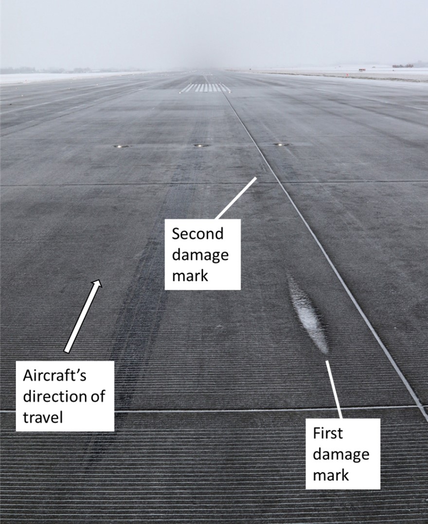
The concrete surface of Runway 06L was slightly damaged. When the bogie beam failed, the landing gear shock strut collapsed onto the surface of the runway. The shock strut’s initial point of contact with the runway damaged the concrete surface over a length of 1.7 m and a maximum depth of 5 cm. The second damage mark, which was 1.8 m long, was superficial (Figure 1).
1.5 Personnel information
The captain and first officer held the appropriate licences and ratings to perform their respective duties for the flight in accordance with existing regulations.
| Captain | First officer | |
|---|---|---|
| Pilot licence | Airline transport pilot licence | Airline transport pilot licence |
| Medical expiry date | 01 April 2022 | 01 May 2022 |
| Total flying hours | 9945 | 22 400 |
| Flight hours on type | 963 | 1300 |
| Flight hours in the 30 days before the occurrence | 46 | 20 |
| Flight hours in the 90 days before the occurrence | 148 | 20 |
| Flight hours on type in the 30 days before the occurrence | 46 | 20 |
| Flight hours on type in the 90 days before the occurrence | 148 | 20 |
| Hours on duty before the occurrence | 5.6 | 5.6 |
| Hours off duty before the work period | 19 | 90 |
1.6 Aircraft information
1.6.1 General
| Manufacturer | Airbus |
|---|---|
| Type, model, and registration | A330-343, C-GFAF |
| Year of manufacture | 1999 |
| Serial number | 0277 |
| Certificate of airworthiness date | 13 January 2000 |
| Total airframe time | 91 282 hours / 14 940 cycles |
| Engine type (number of engines) | Rolls Royce-UK, RB211 Trent 772B-60 (2) |
| Maximum allowable take-off weight | 230 000 kg |
| Recommended fuel type(s) | Jet A, Jet A-1, JP 5, JP 8, No. 3 Jet, TS-1 (GOST) and RT (GOST) |
| Fuel type used | Jet A-1 |
1.6.2 Landing gear
1.6.2.1 Description
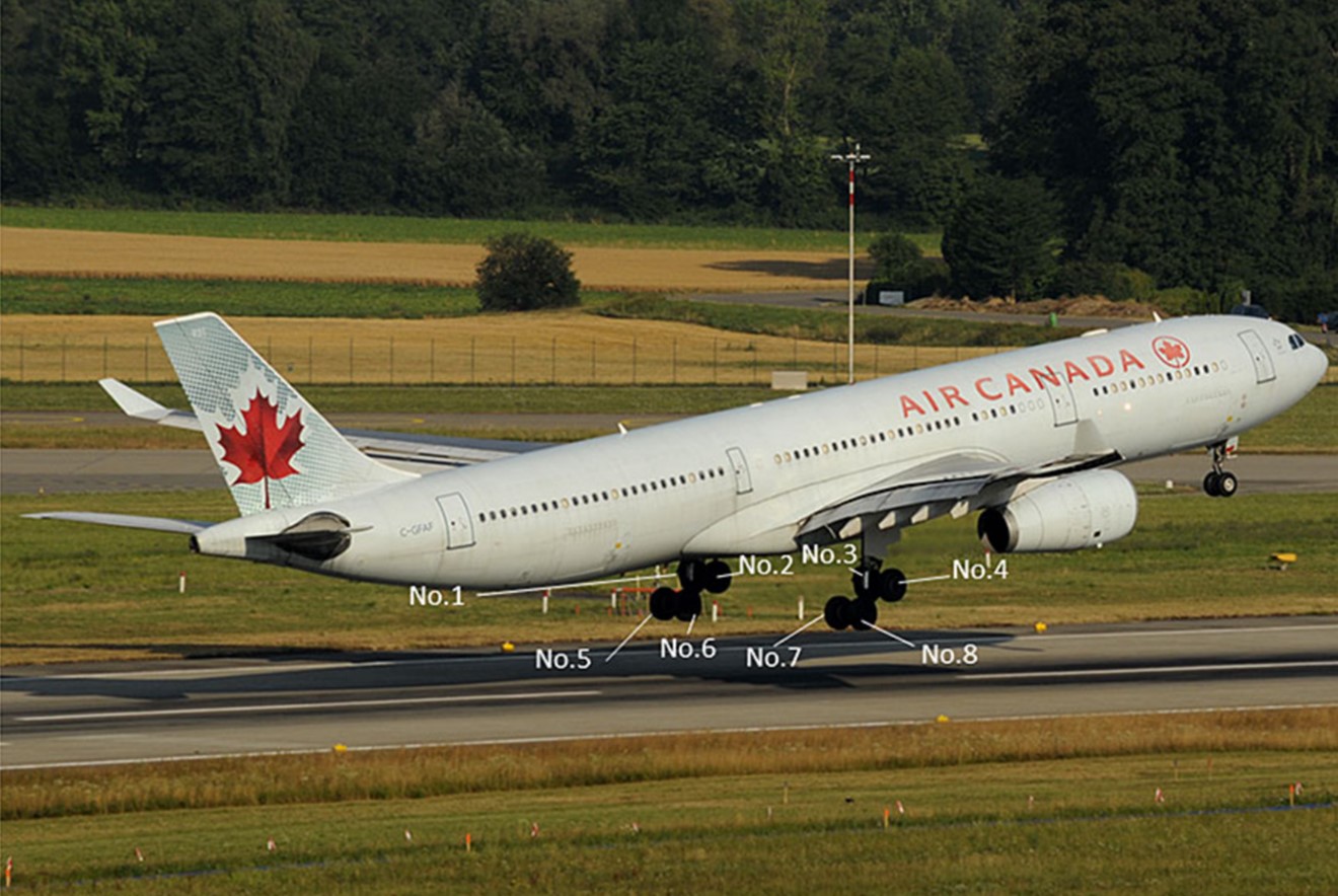
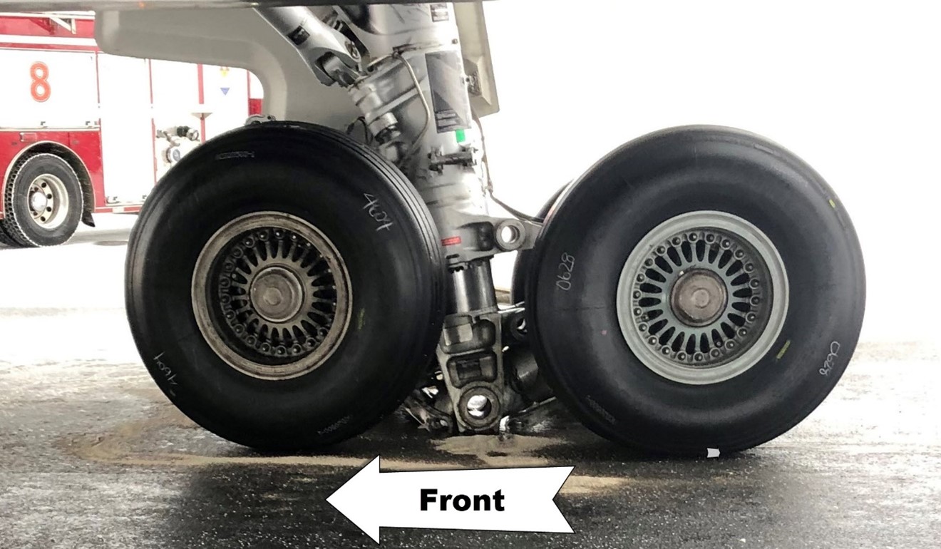
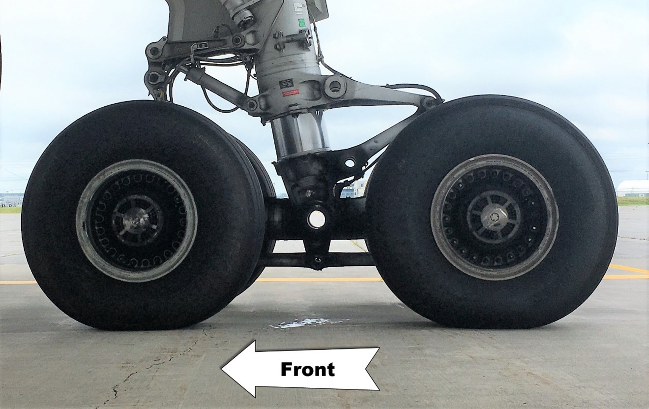
The A330 landing gear consists of a dual-wheel nose gear and 2 main landing gear assemblies with a bogie. Footnote 2 Each bogie has 4 wheels in a twin-tandem configuration. The wheels are numbered from left to right, with 1 to 4 on the front axles and 5 to 8 on the rear axles (Figure 2).
When the aircraft is in flight and the landing gear is down, the bogies are inclined such that when the aircraft lands, the rear tires are the first to touch down on the runway. Therefore, forces are transferred gradually when the wheels touch down. Additionally, the beam position is always the same when the gear is selected up.
Each main landing gear includes the following items (Figure 3):
- bogie beam assembly
- shock strut
- side brace link
- brakes
- wheels and tires
![A330 main landing gear assembly (Source: Airbus, Aircraft Maintenance Manual [AMM], Task 32-41-00-210-808-A [01 April 2019], with TSB annotations)](/sites/default/files/eng/rapports-reports/aviation/2021/a21q0138/images/a21q0138-figure-03.jpg)
The bogie beam is the longitudinal component whose centre point pivots on the shock strut. The beam is a 300MFootnote 3 steel tube with 3 transverse openings: 1 in the centre, where the joint axis connects the bogie to the shock strut, and 2 others at the ends, where the 2 axles pass through. The brake and wheel assemblies are mounted on the axles. Two aluminum-bronze alloy bushings are installed in each opening where an axle passes through, to protect the beam and axle base metal.
Various processes and materials are used to protect the bogie beam. The base metal is covered with a layer of cadmium, which is then coated with a primer. Some parts are chrome-plated. The outer lower part of the beam is coated with a polysulphide layer to protect it from gravel. A polyurethane topcoat is then applied to all of it, except the chrome-plated parts. An Ardrox AV100D corrosion-inhibiting compound is also applied to the inner surface of the beam.
1.6.2.2 History of the right main landing gear
The right main landing gear assembly had been installed on the aircraft on 15 September 2020 after being overhauled. At the time of installation, the assembly had accumulated 79 011 hours and 16 062 flight cyclesFootnote 4 and the bogie beam had accumulated 7715 hours and 1945 cycles. According to the Airbus A330 Airworthiness Limitations Section,Footnote 5 the life limit for the occurrence bogie beam is 75 000 hours and 46 000 cycles, while the landing gear assembly does not have a life limit.
Aircraft records show that the bearings on the No. 4 wheel failed 2 flight cycles before the occurrence flight.
1.6.3 Wheel bearings
1.6.3.1 General
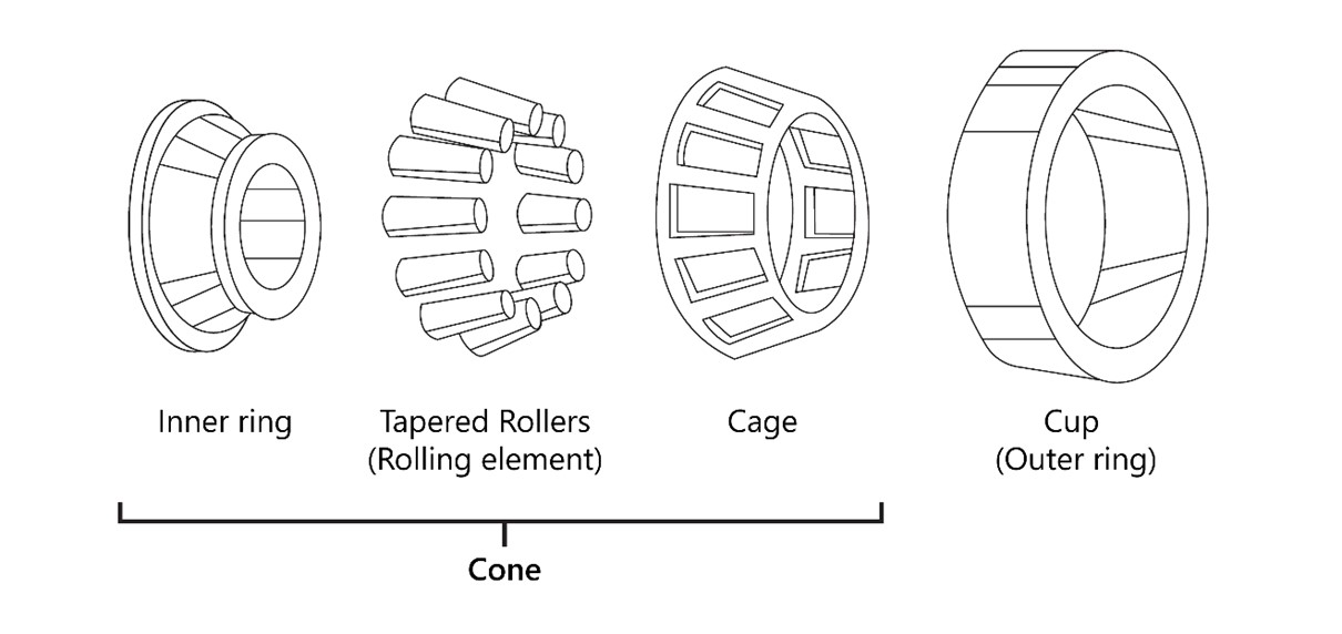
A tapered wheel bearing has 2 main parts: the cup and the cone. The cone itself consists of the inner ring, rollers and the cage, which holds the rollers on the inner ring (Figure 4). The bearings do not have a manufacturer-established life limit. They are inspected and replaced only if a visual inspection reveals a deficiency.
1.6.3.2 Bearing failure
After the BRAKES HOT message for the No. 3 brake appeared on the ECAM while the occurrence aircraft was taxiing on 17 December, maintenance personnel inspected the No. 3 wheel and did not note anything unusual. However, the personnel did notice that the No. 4 wheel was completely off-centre, and the wheel hub was broken. The technicians removed the damaged wheel with the intention of installing another one temporarily, until the aircraft could be towed to the maintenance hangar. However, given that the associated brake unit could not be removed on site, the personnel were unable to install a temporary wheel.
The aircraft was then towed to the hangar with one wheel missing. Given that the maintenance personnel were unable to remove enough fuel, the aircraft’s weight was approximately 190 000 kg, i.e., 18 000 kg more than the maximum towing weight recommended by Airbus. To determine whether this overweight towing with a missing wheel could have had an impact on the bogie beam, the exact data were sent to Airbus, who determined that the forces exerted had not exceeded the design limitations and had not contributed to the beam failure.
Maintenance personnel had to cut the axle protective sleeve into several pieces to release the sleeve and remove the brake unit.
The landing gear inspection revealed the following damage:
- The No. 4 wheel and its associated bearings were destroyed.
- The No. 4 brake unit had been severely damaged by friction with the off-centre wheel.
- The axle protective sleeve showed signs of friction and was welded to the axle.
- The damage to the axle made it impossible to repair.
- The visible face of the front right beam bore bushing showed signs of friction over more than 260°.
- The leads on the temperature sensors for the No. 3 and No. 4 brakes were reversed, hence the overheating indication for the No. 3 wheel rather than the No. 4 wheel.
To assess the extent of the damage and the corrective action to be taken, the technicians used the information available and their observations. They consulted publications in effectFootnote 6 for the occurrence aircraft to determine which existing procedures applied to the situation.
Among the inspections indicated in the maintenance manual, the following inspections were performed:
- Inspection of the aircraft after a tire burst or tread throw or wheel failure;Footnote 7
- Inspection after brake overheat;Footnote 8
- Inspection for discoloration of the overheat indication paint.Footnote 9
No further deficiencies were discovered beyond those already noted during the landing gear inspection.
Maintenance personnel replaced the wheel, the wheel bearings, the brake unit, the axle protective sleeve, the front axle, and the associated bushings on the bogie beam. These bushings were located where the beam failed during the occurrence.
1.6.4 Weight and balance
The occurrence aircraft has a maximum landing weight of 185 000 kg. According to the flight data recording for 25 December, its weight at touchdown was 146 474 kg. The maximum vertical acceleration recorded was 1.158g, which is within the vertical acceleration limits for a normal landing. The maximum vertical acceleration was recorded when the main landing gear’s front wheel tandem touched the runway. Slight variations in force occurred in the next few seconds, but no noticeable increase was recorded.
The centre of gravity was within the prescribed limits.
1.7 Meteorological information
The aerodrome routine meteorological report for CYUL issued at 1100 on 25 December 2021 indicated the following:
- winds from 030° true,Footnote 10 at 15 knots;
- visibility of 15 statute miles;
- light snow;
- overcast ceiling 2000 feet above ground level;
- temperature −7 °C, dew point −11 °C; and
- altimeter setting 29.59 inches of mercury.
According to the runway surface condition replacing NOTAM (NOTAMR), valid at 1113 on 25 December, conditions were the following over the entire length of Runway 06L:
- runway condition code 5;Footnote 11
- 10% of the surface covered by ¼ inch dry snow;
- 90% wet surface;
- cleared width: 180 feet;
- chemical treatment;
- remaining width covered by 1 inch dry snow; and
- low drifting snow.
1.8 Aids to navigation
Not applicable.
1.9 Communications
Not applicable.
1.10 Aerodrome information
Aéroports de Montréal (ADM), a not-for-profit corporation, operates CYUL in accordance with the standards stipulated in Transport Canada’s (TC) publication Aerodrome Standards and Recommended Practices, known as TP 312.
CYUL has 2 parallel runways (06L/24R and 06R/24L), an intersecting runway (10/28), a number of taxiways and several aprons. At the time of the occurrence, Runway 06L was the active runway. Runway 06L/24R is 11 000 feet long and 200 feet wide, with grooved concrete.Footnote 12
1.11 Flight recorders
The aircraft was equipped with a cockpit voice recorder and a digital flight data recorder. Both recorders were removed from the aircraft and sent to the TSB Engineering Laboratory in Ottawa, Ontario, where the data were downloaded and analyzed.
1.12 Wreckage and impact information
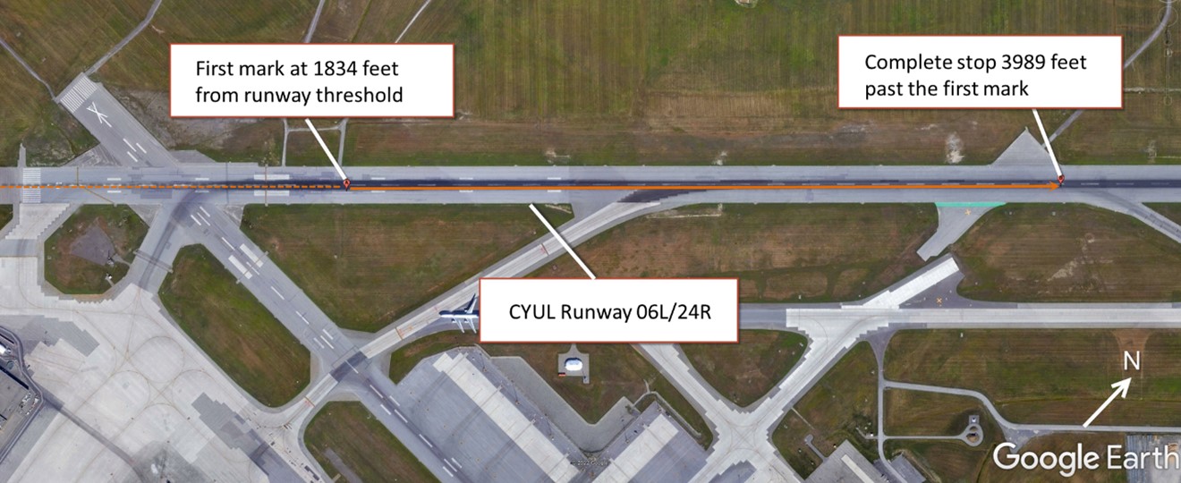
According to the damage observed on the runway by TSB laboratory personnel who examined the runway, the landing gear failure occurred 1834 feet beyond the runway threshold. Various parts of the right main landing gear broke off and were found between the failure location where the first damage mark was left on the runway and the location where the aircraft came to rest, which was 3989 feet further (Figure 5).
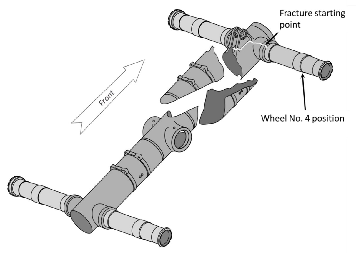
The bogie beam was broken in front of the shock strut hinge. The forward part, including the axle for the No. 3 and No. 4 wheels, was separated completely, and was only held in place by various hydraulic lines, electrical harnesses, and the pitch trimmer system arm. The tire on the No. 8 wheel had been perforated by debris produced by the fracturing of the beam. The lower part of the landing gear strut was abraded up to the hinge. The attachment points of the brake anti-rotation rods were abraded completely, and the rods were no longer being held to the strut (figures 6 and 7).
The preliminary examination of the fracture surfaces drew the investigators’ attention to the area of the front right bore, where the aluminum-bronze bushing was installed near the No. 4 wheel. The fracture surface at this location (Figure 8) had a different texture than the other fractures over approximately 1 cm2.
Other than the abrasion caused by contact with the runway, the shock strut was in good condition and functioning properly.
The wheels and their bearings, along with the brakes, were also in good working order.
1.13 Medical and pathological information
According to information gathered during the investigation, there was no indication that the pilots’ performance was affected by medical or physiological factors.
1.14 Fire
Not applicable.
1.15 Survival aspects
Not applicable.
1.16 Tests and research
1.16.1 TSB laboratory reports
The TSB completed the following laboratory reports in support of this investigation:
- LP002/2022 – CVR Download
- LP003/2022 – Runway Survey
- LP063/2022 – Main Landing Gear Bogie Beam Fracture Examination
1.17 Organizational and management information
1.17.1 Air Canada
Air Canada conducts its activities in accordance with the requirements of subparts 705 and 573 of the Canadian Aviation Regulations (CARs). It holds an air operator certificate and an approved maintenance organization (AMO) certificate.
Air Canada’s maintenance personnel must comply with the policies, procedures, and standards that are explained in detail in the maintenance control manual Footnote 13 and the maintenance policy manual. Footnote 14
Air Canada’s AMO certificate, approved by TC pursuant to existing regulations, allows Air Canada to perform all non-specialized maintenance tasks on the occurrence aircraft type, as well as certain tasks in the specialized maintenance categories, Footnote 15 which are indicated on the certificate. For all other specialized maintenance, Air Canada must use AMOs specialized in the various types of work. Specialized maintenance on landing gear is not included in Air Canada’s AMO certificate.
1.17.2 AAR Landing Gear Services
AAR Landing Gear Services (AAR), located in Miami, Florida, United States, is a repair station approved by the Federal Aviation Administration (FAA) of the United States to provide specialized maintenance services on landing gear components, including the A330 landing gear. To guide and assist technicians, for each contract, AAR’s engineering department produces a process router that describes the work to be performed by the technicians. The work is assessed, then broken down into various operations. Each operation must be signed by the technician who performed it. The operations, which may be a note or an action, are generally in sequential order. This order is based on the approved documentation for the work to be performed, the company’s experience in performing the work, and the inspection points required.
The use of process routers is widespread in the field of aircraft maintenance because they offer a number of benefits, which include:
- presenting, in a logical sequence, the various steps necessary to complete a task;
- incorporating cautions;
- defining inspection points;
- ensuring continuity between the various parties involved; and
- providing written proof that each operation has been completed.
Given that bushing replacement is not one of the repairs described in the landing gear manufacturer’s component maintenance manual (CMM), AAR engineers used the Disassembly and Assembly sections of the CMM and combined them into one operation on the process router. This single operation included several actions that could be performed by a number of technicians at different times, but only required the signature of the technician to whom the operation had been assigned.
1.17.3 Airbus
The A330 is designed and assembled by the aircraft manufacturer, Airbus. Airbus is responsible for producing the instructions necessary for the continued airworthiness of the aircraft, including the aircraft maintenance manual (AMM). These instructions enable AMOs such as Air Canada to determine which maintenance tasks they can perform under their AMO certificate.
1.17.4 Safran Landing Systems
Safran Landing Systems (Safran) is the designer and builder of the A330 landing gear. Safran is responsible for producing the instructions for the continued airworthiness of the components the company makes and provides to aircraft manufacturers. These instructions are namely found in the CMM. The CMM instructions are typically used by AMOs that perform specialized maintenance and are usually organized in the following sections:
- Description and Operation
- Testing and Fault Isolation
- Disassembly
- Cleaning
- Check
- Repair
- Assembly
- Fits and Clearances
- Illustrated Parts List
1.17.5 Maintenance process
The A330 AMM describes the procedure that an AMO must follow to replace an axle on the main landing gear. This procedure is based on Service Bulletin A33/34-32-300Footnote 16 issued by Safran, the landing gear manufacturer. According to this procedure, the bore bushings must be inspected. If a bushing is damaged, the AMO performing the work has 3 options:
- contact the landing gear manufacturer to obtain engineering instructions;
- send the bogie beam to an AMO authorized to perform specialized maintenance on this model of landing gear; and
- replace the bogie beam.
Following the incident on 17 December, Air Canada chose the second option and asked AAR to replace the 2 bushings on the beam and the front axle.
Air Canada and AAR agreed that AAR technicians would go to Montréal, Quebec, to perform the work rather than sending the bogie beam to the AAR workshop in Florida.
The AAR technicians were tasked with removing the damaged axle from the beam, replacing the 2 bushings, boring the bushings, and installing a new axle. The Air Canada technicians had to prepare the bogie beam for AAR. After the AAR technicians completed their work, the Air Canada technicians had to reassemble the beam and landing gear.
The first AAR technicians arrived at CYUL on the evening of 19 December. The next day, the axle was removed using the procedure described in the Safran service bulletin.Footnote 17 First, the axle was released from the parts holding it in place in the bogie beam. Then, the axle was released from the bushings on the beam.
Even though the axle is then only being held in place by its dimensional interference with the bushings, a hydraulic unit applying a minimum force of 20 tonnes is needed to push and release the axle from the bushings on the beam. The CMM does not specify the disassembly procedures for removing the bushings. The AAR technicians removed them using an adaptor plate, a long aluminum punch, and a hammer.
The technicians then visually inspected the bores on the beam in which the new front axle bushings were going to be inserted and they found no deficiencies. The technicians checked the bore sizes but did not note them down. Although it is common practice to do so, it is not required.
The AAR technicians installed the new bushings on 22 December. To do this, the new bushings were cooled in a liquid nitrogen bath, which made the metal contract, making it easier to insert the bushings in the bores. They were then inserted using the hydraulic unit, until the bushing shoulder was perfectly flush with the wall of the beam. To avoid any shifting of parts, pressure is maintained until all components return to room temperature.
The next day, 23 December, the bushings were bored to the final inner dimension stipulated in the beam CMM.Footnote 18
The AAR technicians then prepared the axle for installation. To do this, the axle is plunged in liquid nitrogen to make it contract. The bushings and bogie beam are heated to a maximum temperature of 60 °C. The combined effect of the contraction of the axle and the expansion of the bushings make it possible to properly position the axle in the bogie beam. The axle was then inserted in the beam and held in position until the assembly returned to room temperature.
Once the AAR technicians had completed their work, the Air Canada technicians reassembled the bogie beam and landing gear, and the aircraft was returned to service.
1.18 Additional information
1.18.1 Bogie beam assembly technical examination
Safran was designated to conduct a technical examination of the fractured bogie beam assembly. To prepare for the technical examination, the wheels and brakes were removed from the beam at the Air Canada facilities in Montréal under TSB supervision. No anomalies pertaining to the previous assembly were noted while these parts were being disassembled.
The following parts were sent to the Safran workshop in Gloucester, United Kingdom, for technical examination:
- the 2 main parts of the bogie beam, with the axles and bushings in position;
- the fragments recovered from the beam; and
- the 2 front axle protective sleeves.
The following parts, which were removed after the incident on 17 December, were also sent for technical examination:
- the parts of the No. 4 wheel sleeve that had been cut up;
- the damaged axle; and
- the 2 removed bushings.
1.18.1.1 Laboratory examination of bogie beam fragments
As part of the technical examination, the bogie beam fragments were examined in a laboratory under TSB supervision. Initial visual signs on the beam led investigators to suspect localized overheating of the base metal near the No. 4 wheel. Safran then performed a fractographic analysis of the fragments.
The fracture starting point was located at the point of contact between the end of the bogie beam and the bushing. The forward part of the beam was then cut against the fracture (approximately 180°) to allow the axle and bushings to be released without risking damage to critical surfaces.
When a material fractures, the fracture surfaces bear traces that may indicate the cause of the fracture and how it spread. The fracture surfaces showed chevron-shaped markings, which are associated with the rapid spread of a fracture. In examining the precise shape of the chevrons, it was possible to determine the direction in which the fracture spread, as well as the starting point of the fracture.
A closer examination was carried out with a binocular microscope, using approximately 10X magnification. An incipient secondary crack was discovered near the main fracture, as well as discoloration and cadmium clusters on the chamfer, indicating that the cadmium had reached its melting pointFootnote 19 after an overheating, and had then resolidified (Figure 9).

The inner surface of the beam had scoring damage on the protective layers, and the Ardrox corrosion-inhibiting compound was missing in several spots in the area where the bushings were replaced. Safran’s Service Bulletin A33/34-32-300Footnote 20 has a step that includes the inspection and repair of the protective layers before installation of the axle.
The beginning of the Assembly section in the CMMFootnote 21 states that technicians must ensure that parts are clean and that the dimensions comply with those stated in the applicable section. The Assembly section does not provide a specific step for inspecting surfaces to identify any potential defects in the protective layers or the base metal. The Check section of the CMM provides criteria for inspecting parts, but this section was not used when the axle and bushings were replaced.
The protective layer on the beam, where the bushing shoulder contacts the surface, was blackened over approximately 260° of the circumference, and there was a clear transition between the blackened area and the intact area. Droplet-shaped cadmium accumulations were visible on the chamfer, and a second crack was discovered approximately 20 mm from the main fracture.
It was then decided to conduct 2 different non-destructive tests to determine if overheating had occurred: the Barkhausen noise analysis and the nital etch test.
1.18.1.1.1 Barkhausen noise analysis
The Barkhausen noise analysis is based on variations in the magnetic flux of ferromagnetic material such as 300M steel, which was used to fabricate the bogie beam. These variations indicate that the base metal has been altered, but a more thorough examination is needed to determine the exact nature of this alteration.
This type of testing can be performed using a hand-held device, without having to remove the protective layers of the surface being analyzed.
This test revealed a significant difference in the readings between the healthy area and the blackened area, which is a sign that the metal was altered.
1.18.1.1.2 Nital etch test
A second non-destructive test was then performed: the nital etch test. Nital is a nitric acid and alcohol solution, which, when applied to carbon steel, has a different effect on areas where the steel is healthy compared to areas where the molecular structure has been altered, especially by heat.
Nital must be applied to steel that has no protective layer such as paint, a coating, or a primer, which makes the test complicated to perform as part of a maintenance activity other than a complete part overhaul.
The nital etch test determined that the temperature of the bogie beam base metal had exceeded 850 °C in some places.
1.18.1.1.3 Observations from the fragment examination
When a molten metal comes into contact with a solid metal that has a higher melting point, the molten metal may be absorbed into the structure of the base metal. The base metal loses its ductility in the affected area, making it more fragile. Grains of base metal may also separate. These separations are the beginnings of cracks that can spread and progress very quickly. This phenomenon is called liquid metal embrittlement.
On the occurrence bogie beam, the presence of cadmium within the base metal granular structure was identified using a scanning electron microscope. The temperature reached by the beam’s base metal allowed the cadmium protective layer to liquify (melt) and spread between the grains of 300M steel by capillary action, making the steel fragile and resulting in the formation of 2 cracks (Figure 10).
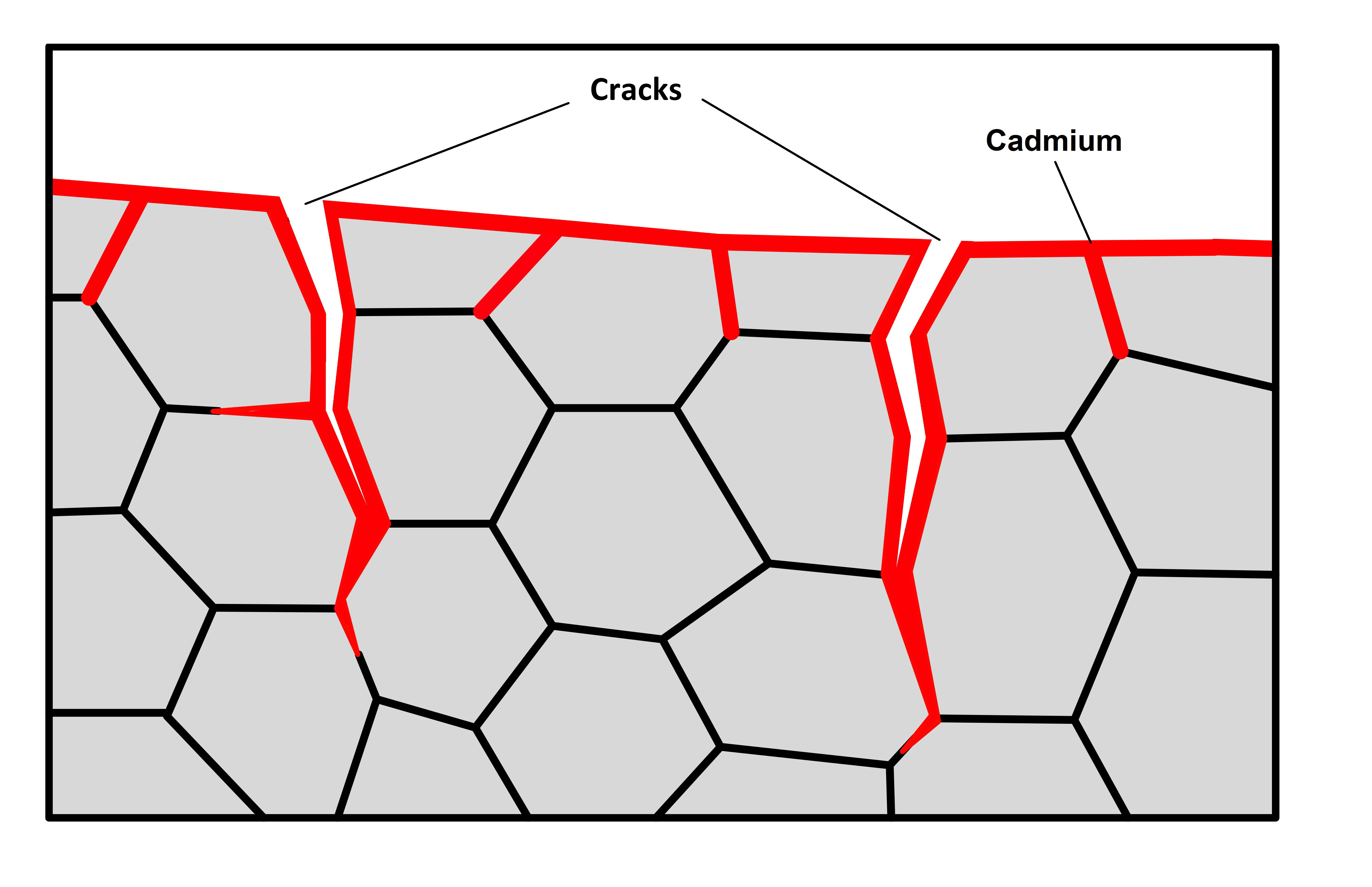
One of these cracks was the cause of the complete fracturing of the bogie beam. Cadmium was also discovered in the cracks, indicating that the cracks formed when the cadmium was still in a liquid state.
1.18.1.2 Examination of the axle
The axle that was removed and replaced following the incident on 17 December was examined. Signs of overheating were observed in several spots on the No. 4 wheel side, not only in the form of discoloration of protective layers, but also in the form of molten metal transferred from the protective sleeve (figures 11 and 12).
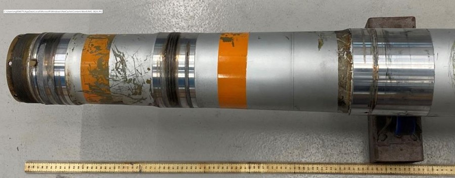
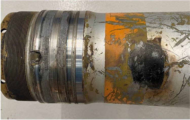
To identify exposure to high heat, axles are equipped with orange indicator strips containing heat-sensitive paint. These strips are placed on the axle at the 2 locations most likely to be exposed to high temperatures in the event of overheated brakes. The colour changes from orange to brown at a temperature of 250 °C, from brown to light grey at 300 °C, and, finally, to off-white when the temperature exceeds 320 °C. The indicator strip closest to the beam at the No. 4 wheel on the axle that was replaced after the incident on 17 December was still its original colour (Figure 12). The strip closest to the nut showed abrasion marks but was still its original colour on most of the remaining surface.
To test whether the indicator strips were working properly, a portion of the axle that had an indicator strip was placed in a temperature-controlled oven. The strip turned grey after 20 minutes of exposure at 320 °C.
1.18.1.3 Examination of the axle protective sleeve
The protective sleeve that was removed after the occurrence on 17 December was fractured at the shoulder. The sleeve had to be cut into 6 pieces when it was still on the axle so that it could be removed. The contact surfaces between the sleeve and the beam bushing had rotational marks, which indicated that the sleeve had rotated around the axle. Furthermore, metal from the beam bushing had transferred to the sleeve at the contact surfaces, possibly due to the friction generated during the sleeve rotation.
These observations determined that the seizure of the wheel bearing had exerted enough rotational force to move the sleeve. The friction between the rotating sleeve shoulder and the beam bushing caused the temperature of the parts that were in contact to increase.
1.18.2 Technical examination of the wheel bearings damaged during the incident on 17 December
The bearings removed after the incident on 17 December were sent to the wheel manufacturer, Goodrich-Messier, for a technical examination. The parts were so damaged that it was impossible to determine with certainty what had caused the failure. A damaged or worn cage would be the most likely cause. Fragments of this cage could have gotten lodged between the rollers and bearing surfaces, and caused a rapid seizure of the parts.
The manufacturer provided the following recommendations on best practices for proper bearing maintenance in its technical report:
- Ensure proper cone assembly inspection occurs to identify cage wear, cage damage and excessive looseness, even if bearings are new
- Ensure proper inspection of roller ends and large rib face to identify scoring damage […]
- Always handle cone assemblies with care when processing, cleaning, and installing. The cage is softer than the other bearing components and is subject to wear or deformation from sharp contact or pressure
- Always ensure the proper nut torque procedure [recommended by the manufacturer] is followed […]
- Always use a properly calibrated torque wrench when installing the nut
- Always apply fresh, clean grease to the bearings within four hours of inspection
- Clean old grease from nut and axle threads
- Ensure the nut rotates easily on axle threads
- Ensure fresh grease is applied to the nut threads and nut face […]
- Ensure the wheel is installed all the way against the inboard axle sleeve shoulder
- Ensure the wheel rotates smoothly during all nut torque operations
- Use a wheel dolly [to raise and align the wheels during installation]
- Ensure the bearing seats are to specification and are clean and free from nicks, dents, and wear.Footnote 22
1.18.3 Bearing failures on other Air Canada aircraft
In 2017, following 2 occurrences involving wheel bearings, Air Canada undertook a comprehensive study into the probable causes of these failures. The study was unable to pinpoint a single contributing factor, but it did propose several possible causes.
The main possible causes were:
- inadequate lubrication or contaminated grease;
- defect missed during a visual inspection;Footnote 23 and
- improper torque applied to the wheel nut.
As a result of this study, Air Canada put several measures in place to reduce the risk of unscheduled bearing replacements, including:
- replacement of all wheel bearings on its fleet of A330s;Footnote 24
- periodic replacement of bearings every 2400 flight cycles, regardless of their condition;
- evaluation and validation of bearing installation procedures and training; and
- calibration of torque wrenches at 6-month intervals rather than 12.
2.0 Analysis
During the landing on 25 December 2021, the bogie beam on the right main landing gear fractured in front of the hinge point. A crack spread all around the beam, causing the forward part to fracture and several parts to fall onto the runway.
The fractographic analysis of the fragments revealed that the fracture starting point was the No. 4 wheel bore, which had undergone maintenance 2 flight cycles before the occurrence. This analysis will focus first on the bogie beam fracture, then on the maintenance performed previously, to identify the causes and contributing factors as well as the risk factors associated with the occurrence.
2.1 Bogie beam failure
2.1.1 First visual examination of the fracture surfaces
When the aircraft is in flight and the landing gear is down, the bogies are inclined such that when the aircraft lands, the rear tires are the first to touch down on the runway. Therefore, forces are transferred gradually when the wheels touch down.
An analysis of the vertical acceleration forces at touchdown indicates that the landing occurred without excessive force and that the maximum vertical acceleration was recorded when the main landing gear’s front wheel tandem touched the runway. Slight variations in force occurred in the next few seconds, but no noticeable increase was recorded, indicating that the beam quite likely failed when the front wheel tandem touched down.
The damage marks left on the runway led to the same conclusion, which was that the beam very likely fractured on touchdown and the landing gear collapsed immediately.
These observations indicate that there was a pre-existing condition and that the failure was not the consequence of an impact.
The fractographic analysis of the beam’s fracture surfaces, conducted by Safran Landing Systems’ (Safran) metallurgical laboratory under TSB supervision, determined that the surfaces showed chevron-shaped markings, which are typically associated with the rapid spread of a fracture. Furthermore, an examination of these chevrons helped to determine the direction in which the fracture spread, as well as the starting point of the fracture. All of the markings observed pointed to the No. 4 wheel bore, where the fracture surfaces had a different granular structure over approximately 1 cm2.
2.1.2 Laboratory examination of the bogie beam fragments
An examination of the fracture surfaces under a scanning electron microscope revealed the presence of cadmium coming from the corrosion-inhibiting protective layer within the base metal granular structure, near where the fracture started. The presence of cadmium indicated that it had reached its melting point and, therefore, overheating had occurred.
After the Barkhausen noise analysis, which revealed that the metal had been altered, a nital etch test determined that the surface temperature of the beam’s base metal (300M steel) had exceeded 850 °C in some places around the bushing shoulder. The weakened steel then led to the formation of 2 cracks.
The investigation determined that the area of overheating was not a result of the occurrence flight. A review of past occurrences was then carried out and it was discovered that brake overheating and a bearing failure had occurred on 17 December on the same bogie. It was then deemed necessary to further study this overheating.
Findings as to causes and contributing factors
Two cracks emanated from a previously undetected area of overheating under the bogie beam bushing. One of the 2 cracks spread and caused a fracture of the No. 4 wheel bore.
Upon landing on 25 December 2021, the fracture emanating from the No. 4 wheel bore spread rapidly and resulted in the bogie beam breaking into several pieces. No longer supported by the wheels, the shock strut scraped the runway until the aircraft came to rest.
2.2 Brake overheating and bearing failures before this occurrence
2.2.1 Cockpit indication
On 17 December 2021, while the occurrence aircraft was taxiing into position for takeoff, the electronic centralized aircraft monitor (ECAM) generated a BRAKES HOT message for the No. 3 wheel. The crew taxied the aircraft back to the terminal to have the brake inspected by maintenance personnel. Given that the brake temperature sensor leads for the No. 3 and No. 4 wheel brakes had been reversed during a previous maintenance activity, no deficiencies were found with the No. 3 wheel. Because the No. 3 and No. 4 wheels were on the same axle, this reversed overheating indication had no impact on the operational procedures that the pilots had to follow.
2.2.2 Damage assessment
During the inspection after the brake overheating indication, maintenance personnel noted that the No. 4 wheel was completely off-centre and the wheel hub was broken. The preliminary observations were the following:
- wheel bearings destroyed;
- damage to the axle sleeve;
- localized friction damage to the axle; and
- friction damage to the face of the beam bushing.
To assess the extent of the damage and the corrective action to be taken, the technicians used the information available and their observations. They consulted publications in effect for the aircraft to determine which existing procedures applied to the situation.
Finding as to risk
If the brake temperature sensor leads are reversed on the landing gear bogie, the brake overheating indication in the cockpit will be associated with the wrong wheel. Maintenance personnel might then inspect the wrong wheel, and damage could be missed.
2.2.2.1 Brake overheating indication
As a result of the observed damage, the technicians determined that the unscheduled inspection after brake overheat procedure, described in the aircraft maintenance manual (AMM), needed to be carried out. One of the steps in this procedure requires the inspection of the axle overheat indicator strips.
The indicator strip closest to the beam at the No. 4 wheel on the damaged axle was still its original colour, which led the technicians to believe that the assembly had not been exposed to a temperature greater than 250 °C, at which point the strip paint colour begins to change from orange to brown.
Brake overheating generally produces heat that is transmitted to the axle through radiation over a large surface for a relatively long period. In the 17 December occurrence, the considerable mechanical energy produced by the sleeve rapidly rotating around the axle and rubbing against the beam bushing was converted into high localized thermal energy at the friction points. Although the temperature had exceeded 850 °C in some places, the significant metallic mass of the axle rapidly dissipated the heat, which explains why this heat had no effect on the indicator strip closest to the beam.
Finding as to causes and contributing factors
Given that the overheat indicator strip closest to the beam at the No. 4 wheel on the axle was its original colour, applicable procedures allowed for the replacement of the axle and the bogie beam bushing without a thorough damage assessment.
2.2.2.2 Damage to the beam axle bushing
The bogie beam axle bushing showed friction marks on its face, which is normally in static contact with the sleeve. The Safran laboratory report showed that seizure of the wheel bearing had caused the sleeve to rotate and that friction between the sleeve shoulder and the bushing had caused wear and melting damage to the bushing.
Finding as to causes and contributing factors
On 17 December 2021, while the aircraft was taxiing for takeoff, for an undetermined reason, one of the bearings on the No. 4 wheel seized and caused the protective sleeve to rub against the bogie beam bushing, causing localized overheating of the bogie beam base metal.
2.2.3 Bushing replacement
Given that bushings are an integral part of the beam assembly, the technician must consult the component maintenance manual (CMM) for their applicable limits, possible repairs, or replacement. Because bushing replacement is a specialized maintenance task, Air Canada technicians could not perform the task themselves. They had to use the services of the maintenance organization AAR Landing Gear Services (AAR), which was approved to perform this task.
2.2.3.1 Part replacement procedure
AAR technicians replaced the axle and bushings using the process router created by their engineering department and based on existing approved documentation, i.e., the CMM.
However, given that bushing replacement is not one of the repairs described in the CMM, AAR engineers used the Disassembly and Assembly sections of the CMM and combined them into one operation. As a result, this single operation included several actions that could be performed by a number of technicians at different times, but only required the signature of the technician to whom the operation had been assigned. This situation thereby undermined the inherently rigorous process routers and ran counter to the purpose of using them.
Finding as to risk
If maintenance actions that can be carried out by a number of technicians at different times are combined into a single operation on a process router, an action could be omitted or not checked, creating a risk that the maintenance performed will not be safe.
2.2.3.2 Visual inspection of surfaces
During the examination of the beam assembly at Safran’s laboratory, scoring damage was found on the protective layers of the beam’s inner surface. It is likely that this scoring damage was caused when the AAR technicians removed the bushing from the axle. The Disassembly section of the CMM does not provide a specific procedure or the tools required to remove bushings. AAR technicians generally use an adaptor plate placed against the bushing and a long aluminum punch that the technicians hit with a hammer. The punch’s length and weight make it difficult to manoeuvre within the limited space of the beam bore and increase the risk of damage to surrounding surfaces.
In addition to the scoring damage, the examination of the beam assembly conducted for the purposes of the investigation revealed that the Ardrox corrosion-inhibiting compound was missing in several spots in the area where the bushings were replaced.
Safran’s Service Bulletin A33/34-32-300 has a step that includes inspection and repair of the protective layers before installation of the axle. The beginning of the Assembly section in the CMM states that technicians must ensure that parts are clean and that the dimensions comply with those stated in the applicable section.
The Assembly section of the CMM does not provide a specific step for inspecting surfaces to identify any defects in the protective layers or the base metal. The Check section of the CMM provides criteria for inspecting parts, but this section was not used when the axle and bushings were replaced.
Although the scoring damage and missing Ardrox were not considered to be contributing factors to the failure, metal on untreated surfaces is susceptible to premature corrosion, which can reduce a part’s life limit.
Findings as to risk
If scoring and other damage to the inner surface of a bogie beam are not detected during visual inspections, there is a risk that cracks will develop.
If spots of missing corrosion-inhibiting protective layer inside a bogie beam are not identified during visual inspections, there is an increased risk of corrosion.
Examination of the beam assembly revealed signs of localized overheating on the axle. Despite the presence of these signs on the axle, the technicians who assessed the damage ruled out the possibility that the beam metal had overheated. They focused on the following points to arrive at this conclusion:
- The overheat indicator strip closest to the beam on the axle was intact.
- The blackened area showed a clear transition, contrary to what would be expected for the usual spread of heat in metal.
- The surface of the paint immediately around the bushing did not show any signs of excessive heat, such as blistering or gradual discoloration.
The documentation in effect allowed for the replacement of the damaged parts without a thorough assessment of the bogie beam damage. The technicians were focused on what they had to do, which was to replace the axle and bushings using the documentation available at the time to return the occurrence aircraft to service.
Finding as to causes and contributing factors
Given the intact indicator strip, the clear transition between the blackened area and the adjacent protective layer, and the intact paint on the beam around the bushing, the technicians who performed the visual inspection during the replacement of the damaged bushing concluded that the beam was in good condition, even though the bogie beam base metal had overheated.
The report for the laboratory examination conducted by Safran determined that the structure of the 300M steel used to fabricate the beam had been altered, and 2 cracks were present when the axle and bushings were replaced. Some non-destructive tests, such as the Barkhausen noise analysis and the nital etch test, would have identified these deficiencies.
Finding as to causes and contributing factors
Given that the CMM does not provide any specific repair for a bushing replacement, the Disassembly and Assembly sections were used as references. Consequently, the inspection criteria during bushing replacement focused on ensuring the correct dimensions rather than detecting damage, which eliminated the requirement for non-destructive tests.
3.0 Findings
3.1 Findings as to causes and contributing factors
These are conditions, acts or safety deficiencies that were found to have caused or contributed to this occurrence.
- On 17 December 2021, while the aircraft was taxiing for takeoff, for an undetermined reason, one of the bearings on the No. 4 wheel seized and caused the protective sleeve to rub against the bogie beam bushing, causing localized overheating of the bogie beam base metal.
- Given that the overheat indicator strip closest to the beam at the No. 4 wheel on the axle was its original colour, applicable procedures allowed for the replacement of the axle and the bogie beam bushing without a thorough damage assessment.
- Given that the component maintenance manual does not provide any specific repair for a bushing replacement, the Disassembly and Assembly sections were used as references. Consequently, the inspection criteria during bushing replacement focused on ensuring the correct dimensions rather than detecting damage, which eliminated the requirement for non-destructive tests.
- Given the intact indicator strip, the clear transition between the blackened area and the adjacent protective layer, and the intact paint on the beam around the bushing, the technicians who performed the visual inspection during the replacement of the damaged bushing concluded that the beam was in good condition, even though the bogie beam base metal had overheated.
- Two cracks emanated from a previously undetected area of overheating under the bogie beam bushing. One of the 2 cracks spread and caused a fracture of the No. 4 wheel bore.
- Upon landing on 25 December 2021, the fracture emanating from the No. 4 wheel bore spread rapidly and resulted in the bogie beam breaking into several pieces. No longer supported by the wheels, the shock strut scraped the runway until the aircraft came to rest.
3.2 Findings as to risk
These are conditions, unsafe acts or safety deficiencies that were found not to be a factor in this occurrence but could have adverse consequences in future occurrences.
- If the brake temperature sensor leads are reversed on the landing gear bogie, the brake overheating indication in the cockpit will be associated with the wrong wheel. Maintenance personnel might then inspect the wrong wheel, and damage could be missed.
- If maintenance actions that can be carried out by a number of technicians at different times are combined into a single operation on a process router, an action could be omitted or not checked, creating a risk that the maintenance performed will not be safe.
- If scoring and other damage to the inner surface of a bogie beam are not detected during visual inspections, there is a risk that cracks will develop.
- If spots of missing corrosion-inhibiting protective layer inside a bogie beam are not identified during visual inspections, there is an increased risk of corrosion.
4.0 Safety action
4.1 Safety action taken
4.1.1 Airbus
Following this occurrence, Airbus modified the tasks below in the A330 maintenance manual, requesting that operators contact them if damage to the bogie beam or bushings is discovered:
- 05-51-15-200-801 – Inspection of the Aircraft after a Tire Burst or Tread Throw or Wheel Failure
- 05-51-16-200-801 – Inspection After Brake Overheat
- 32-41-00-210-808 – Detailed Inspection of the Axle and Axle Sleeve after a Wheel Bearing Failure
This report concludes the Transportation Safety Board of Canada’s investigation into this occurrence. The Board authorized the release of this report on . It was officially released on .