Power loss of both engines on initial climb
North Star Air Ltd.
Douglas DC-3C Basler Turbo Conversions TP67, C-FKGL
Eabamet Lake, Ontario
The Transportation Safety Board of Canada (TSB) investigated this occurrence for the purpose of advancing transportation safety. It is not the function of the Board to assign fault or determine civil or criminal liability. This report is not created for use in the context of legal, disciplinary or other proceedings. See Ownership and use of content. Masculine pronouns and position titles may be used to signify all genders to comply with the Canadian Transportation Accident Investigation and Safety Board Act (S.C. 1989, c. 3).
Summary
On , at approximately 0140 Eastern Daylight Time, a North Star Air Ltd. Douglas DC-3C Basler Turbo Conversions TP67 aircraft (registration C-FKGL, serial number 19066) was conducting a flight from Fort Hope Airport (CYFH), Ontario, to Pickle Lake Airport (CYPL), Ontario, with 2 flight crew members on board. Shortly after takeoff, both engines (Pratt & Whitney Canada PT6A-67R) lost power simultaneously. The flight crew executed a forced landing on Eabamet Lake, Ontario. After landing, the crew evacuated the aircraft via the main cabin door and swam to shore. The Nishnawbe Aski Police Service responded and took the crew to a nursing station for treatment. Neither flight crew member was injured. The aircraft sustained substantial damage, but there was no post-impact fire. No emergency locator transmitter signal was received by the Joint Rescue Coordination Centre in Trenton, Ontario, at the time of the accident, but one was received approximately 4 hours after the accident. The accident occurred during hours of darkness.
1.0 Factual information
1.1 History of the flight
On 20 June 2019, a North Star Air Ltd. (North Star Air) Douglas DC-3C Basler Turbo Conversions TP67 (DC3-TP67) aircraft (registration C-FKGL, serial number 19066) was conducting a series of visual flight rules flights between Pickle Lake Airport (CYPL), Ontario, and Fort Hope Airport (CYFH), Ontario.
The purpose of the flights was to deliver 5940 L of diesel fuel per trip to the Eabametoong First Nation community, also known as Fort Hope. The aircraft was equipped with one 6815 L flexible bladderFootnote 1 secured to the floor.
The flight crew arrived for duty at 1830Footnote 2 on 20 June 2019 at the North Star Air base in CYPL and fuelled the aircraft. Between 1914 on 20 June and 0110 on 21 June, the aircraft conducted 3 flights from CYPL to CYFH and return, transporting 5940 L of cargo fuel on each flight. The offloading of the diesel fuel took about 20 minutes and required the flight crew to set up a pump and secure hose connections.
Before departing CYFH on the occurrence flight, the crew conducted the before-takeoff checklist, which requires the propeller automatic feathering system to be armed for takeoff; however, the crew did not arm this system.
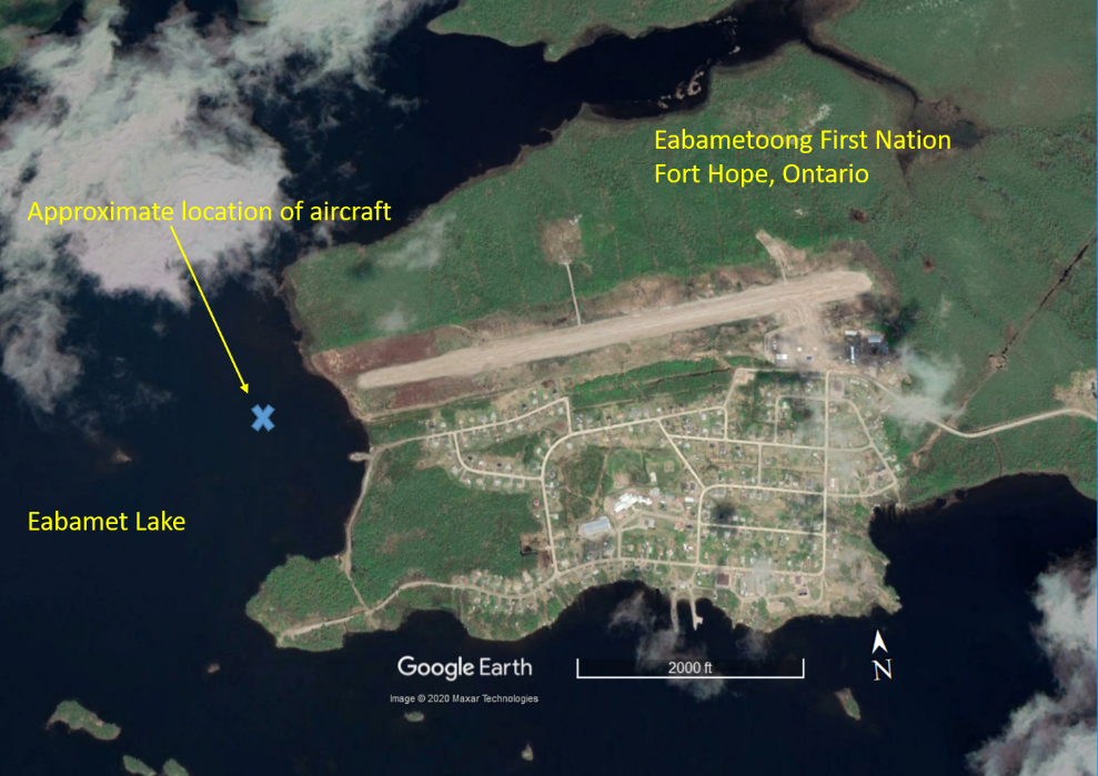
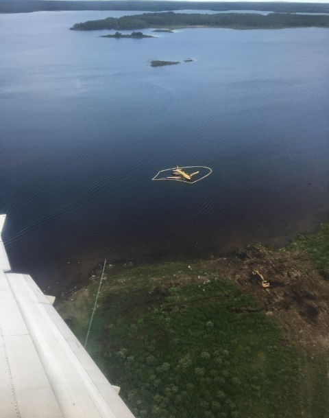
At approximately 0140, the aircraft departed CYFH with the first officer acting as the pilot flying (PF), seated in the right seat, and the captain acting as the pilot not flying (PNF), seated in the left seat. Shortly after takeoff, the PF called for the landing gear to be retracted. The PNF then selected the gear up at approximately 200 feet above ground level (AGL). Both engines subsequently lost power simultaneously, and the flight crew executed a forced landing on Eabamet Lake, Ontario, in total darkness (Figure 1).
The aircraft fuselage remained intact and immediately began to fill with water. The flight crew retrieved the survival kit, evacuated the aircraft via the main cabin door, and swam to shore.
Once on shore, the flight crew started a fire to warm up. The fire was noticed by a patrolling officer of the Nishnawbe Aski Police Service, who responded and transported the flight crew to the nursing station at the Eabametoong First Nation Band Office for a medical assessment. Neither flight crew member was injured.
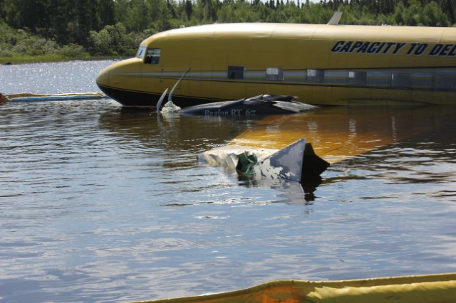
The aircraft sustained substantial damage, but there was no post-impact fire. The aircraft remained floating in the water.
No emergency locator transmitter (ELT) signal was received by the Joint Rescue Coordination Centre in Trenton, Ontario, at the time of the accident. However, the ELT did activate approximately 4 hours after the accident. The investigation did not determine why the ELT activation was delayed.
1.2 Injuries to persons
| Crew | Passengers | Others | Total | |
|---|---|---|---|---|
| Fatal | 0 | - | - | 0 |
| Serious | 0 | - | - | 0 |
| Minor/None | 2 | - | - | 2 |
| Total | 2 | - | - | 2 |
1.3 Damage to aircraft
The aircraft was substantially damaged.
1.4 Other damage
There was a potential for water contamination due to oil and fuel leaking from the aircraft; however, water contamination tests conducted on behalf of North Star Air after the accident indicated that the water quality was within the Provincial Water Quality Objective criteria established by the Province of Ontario.Footnote 3
1.5 Personnel information
| Captain | First officer | |
|---|---|---|
| Pilot licence | Airline transport pilot licence | Commercial pilot licence |
| Medical expiry date | 01 April 2020 | 01 February 2020 |
| Total flying hours | 14 000 | 4000 |
| Flight hours on type | 2500 | 800 |
| Flight hours in the 7 days before the occurrence | 37.4 | 37.4 |
| Flight hours in the 30 days before the occurrence | 90.4 | 90.4 |
| Flight hours in the 90 days before the occurrence | 178 | 223 |
| Flight hours on type in the 90 days before the occurrence | 178 | 223 |
| Hours on duty before the occurrence | 8 | 8 |
| Hours off duty before the work period | 11 | 11 |
The captain had joined North Star Air as a captain in April 2017 and had completed his initial training on 03 July 2017. He held a valid Category 1 medical certificate with no restrictions. His last DC3-TP67 pilot proficiency check was successfully completed on 01 March 2019.
The first officer had joined North Star Air as a first officer in May 2018 and had completed his initial training on 25 June 2018. He held a valid Category 1 medical certificate with no restrictions. His last DC3-TP67 pilot proficiency check was successfully completed on 01 June 2019.
1.6 Aircraft information
1.6.1 General
The occurrence aircraft was built in the U.S. by the Douglas Aircraft Company in 1942 and was originally equipped with 2 Twin Wasp R-1830 piston engines. It is a low-wing aircraft with retractable main landing gear and a non-retractable tailwheel.
The regulations in effect at the time the aircraft was built stipulated that the maximum number of occupants, including flight crew, for this model of aircraft was 35. The current regulations contain the same stipulation.Footnote 4
1.6.2 Supplemental type certificates
Before being imported into Canada, the aircraft was modified in accordance with several supplemental type certificates (STCs). Among these were the following:
- Transport Canada (TC) STC SA00-9,Footnote 5 which was based on STC SA4840NM, issued by the U.S. Federal Aviation Administration (FAA), and included approval for the following airframe modifications:
- Pratt & Whitney Canada turbo-prop engines PT6A-67R
- Hartzell HC-B5MA-3/M11276 or M11691N, K model propellers
- Modified fuel systemFootnote 6
- FAA STC ST302CH,Footnote 7 which approved the addition of shoulder harnesses to the flight crew restraint systems
- TC STC SA08-51,Footnote 8 which was based on FAA STC ST00435DE and approved the reconfiguration of the aircraft for a maximum seating of 19 passengers
TC issued a Certificate of Airworthiness for the aircraft on 27 February 2014.
| Manufacturer | Douglas Aircraft Company |
|---|---|
| Type, model and registration | DC3-TP67, C-FKGL |
| Year of manufacture | 1942 |
| Serial number | 19066 |
| Certificate of airworthiness/flight permit issue date | 27 February 2014 |
| Total airframe time | 22 769.5 hours |
| Engine type (number of engines) | Pratt & Whitney Canada PT6A-67R (2) |
| Propeller/Rotor type (number of propellers) | Hartzell HC-B5MA-3M (2) |
| Maximum allowable take-off weight | 30 000 lb |
| Recommended fuel type(s) | Jet A, Jet A-1, Jet B |
| Fuel type used | Jet A-1 |
North Star Air had completed a 150-hour maintenance inspection on 11 June 2019 and a daily inspection on 20 June 2019. There were no reported defects before the occurrence flight.
The aircraft had a basic empty weight of 16 429.7 pounds, and the recorded takeoff weight for the occurrence flight was 18 416 pounds. The flexible fuel bladder was empty on the occurrence flight. The investigation determined that the weight and centre of gravity were within the prescribed limits.
1.6.3 Throttle quadrant
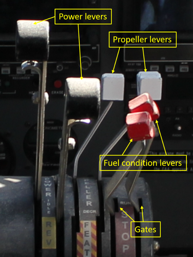
The throttle quadrant consists of power levers, propeller levers, fuel condition levers, and rotary friction locks (Figure 2).
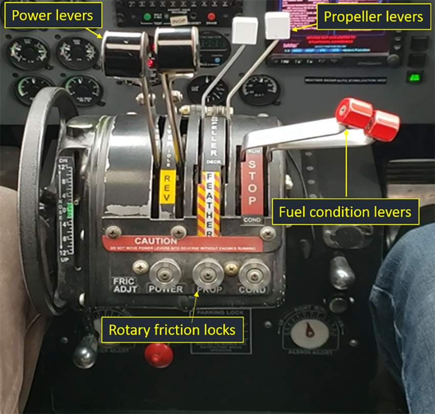
There is one set of levers for each engine and associated propeller. Both pilots have functional reach to all sets of levers. The design uses varied colours, sizes, and shapes to facilitate visual and tactile identification. A colour and shape coding and grouping for these levers is common throughout the industry.
The fuel condition levers in this aircraft are offset to the right of the quadrant and angled toward the right seat. The offset is to ensure that these levers do not interfere with the propeller levers. The fuel condition levers stop fuel flow to the engines when they are moved into the down position (STOP). To allow fuel feed to the engines, the fuel condition levers are placed in the up position (RUN) and are secured in that position by means of a gate. The design of the fuel condition levers requires the flight crew to make a dual-axis motion; to bring down each fuel condition lever from the gate, a pilot needs to shift the lever slightly to the left and then down. With this design, it is possible to move both fuel condition levers at the same time with one hand.
On the occurrence aircraft, the fuel flow to the engines is cut when the levers are moved down past the “O” of the word “STOP” (this position can vary from one aircraft to another).
Rotary friction locks, also shown in Figure 2, are located below each lever and allow the flight crew to apply resistance to the levers.
1.6.3.1 Ergonomics
The design of the controls, the displays, and their layout aims to balance functionality, effectiveness, usability, and safety. The layout of the controls in the cockpit takes into account the importance, frequency and sequence of use, or grouping by function. There are options to protect against an unintentional movement of a control, when a pilot accidentally bumps and moves a control or actuates the wrong control. There are trade-offs between measures to prevent unintentional movement and usability, because such measures may make controls more difficult to operate. Cockpit discipline and procedures also reduce the risk of unintentional movement. Measures to reduce the likelihood of unintentional movement are as follows:Footnote 9,Footnote 10
- Tactile and visual cues
- Location and orientation of controls
- Sufficient resistance
- Complex operation such as dual-axis motion
- Locking or interlocking mechanisms
- Restricted access via a physical guard, recess, or position outside the normal reach of the pilot
Transportation Safety Board of Canada (TSB) investigators conducted a trial of unintentional movement of the fuel condition levers while reaching for the mechanical safety latch control handle and the landing gear control handle, located on the cockpit floor between the pilot seats (Figure 3), in a DC3-TP67 representative of the occurrence aircraft. This trial was performed during the day while the aircraft was on the ground, with the engines turned off, in a static environment. While the aircraft is on the ground, it is impossible to lift the landing gear handles. During the initial phase of a climb at night, lighting is limited in the cockpit, the aircraft attitude is pitched nose-up, and the crew is in a dynamic environment. The main observations from the TSB’s limited trial were as follows:
- When a pilot is seated in the right seat, if the pilot’s extended left arm moved aft past the throttle quadrant and contacted the fuel condition levers in a continuous movement, it was difficult to simultaneously move both fuel condition levers out of their gates and down. Contact with the levers is physically noticeable.
- When a pilot is in the left seat, unintentional movement of the fuel condition levers was more likely with the hands rather than the arms.
- An accidental movement of the fuel condition levers was much easier if both levers were not secured in their individual gates.
- When the rotary friction locks were adjusted to a low level, the resistance of the fuel condition levers was still significant enough to help prevent an accidental movement.
- When the pilot in the left seat wears long sleeves, particularly with cuffs on a flight suit,Footnote 11 the possibility of snagging the fuel condition levers was higher, although accidental movement of only the right fuel condition lever was more likely.
1.6.4 Aircraft fuel system
The occurrence aircraft is equipped with the standard Basler Turbo Conversions fuel system. This system includes 2 tanks in the centre section of the left-hand wing and 2 tanks in the centre section of the right-hand wing. These tanks are identified as main and auxiliary. The auxiliary tanks transfer fuel to the main tanks, which supply fuel to their respective engines.
The fuel must be mixed with fuel system icing inhibitor in a concentration ranging from a minimum of 0.06% to a maximum of 0.15%. If the fuel is not pre-mixed at the refinery, the additive must be mixed during aircraft refuelling. This inhibitor is added to prevent the fuel filters from clogging due to fuel icingand to reduce the risk of engine flameout.
The investigation determined that the fuel delivered to the operator was pre-mixed and met the concentration levels by volume specified in the airplane flight manual supplement (AFMS).Footnote 12
The main tanks contain the main and standby fuel-boost pumps. The pumps are submerged in fuel within the tank. The main fuel-boost pumps normally run from engine start to shutdown; the standby pumps, when selected to AUTO, automatically run when there is a failure of the aircraft main fuel-boost pump.
The aircraft fuel selector and control valves are electrical and are operated by selecting and switching from the fuel system control panel in the cockpit.
1.6.5 Engine ignition system
The PT6A-67R engine employs a solid-state, capacitor-type electronic exciter unit that delivers simultaneous high voltage to 2 independent spark ignitors. The system continues to operate if one ignitor is unserviceable. The ignition system functions when the ignition switches are set to START or CONT (continuous mode).Footnote 13
The AFMS indicates when the ignition switches should be set to CONT. In Revision 13 of the AFMS, issued on 10 January 2018, a statement was added indicating that the ignition switches should be set to CONT during the before takeoff (final) check.Footnote 14
The North Star Air standard operating procedures (SOPs) and checklists do not indicate to pilots when to set the ignition switches to CONT.
1.6.6 Engine start procedure
The Pratt & Whitney Canada PT6A-67R, like all turbine engines, requires a continuous flow of fuel and air for operation.
When the aircraft is on the ground, before the first engine is started, the power levers are set to IDLE, the prop levers are in the FEATHER position, and the fuel condition levers are in the STOP position. In addition, the standby fuel pumps are set to AUTO and the main fuel pumps are set to ON.Footnote 15
The first engine is then started by setting the associated ignition switch to START and pushing the START button to engage the starter. Once the engine has accelerated and stabilized above 12% of the gas generator speed (Ng), the fuel condition levers are placed in the RUN position and secured in the gate. This introduces fuel to the engine, leading to fuel ignition, and the engine accelerates. Once the engine has reached approximately 50% Ng, the starter automatically disengages, and the pilot can control the engine through the power levers. This procedure is repeated to start the second engine.Footnote 16
1.6.6.1 Relighting engines in flight
An engine that has flamed out in flight due to a momentary disruption of airflow or fuel to the engine should be automatically relighted if the ignition system switches are in the CONT position.
North Star Air’s SOPs also provide flight crews with 2 different emergency procedures for relighting engines in flight: a propeller windmilling procedure and a starter assist procedure.Footnote 17 These procedures are based on the AFMS.Footnote 18
The procedure for relighting with the propeller windmilling procedure requires an aircraft speed greater than 160 knots indicated airspeed (KIAS). This allows the engine to obtain sufficient Ng speed (minimum 10%), but, to do so, the aircraft may need to descend. This procedure is completed without starter assist.
The SOPs state the following:
CAUTION: In[-]flight engine restarts using the prop wind milling procedure are not recommended other than in the event of a true emergency. Since there is a high likelihood of engine damage during the wind milling restart, it should not be used in training sessions but only in the case of in-flight emergency.Footnote 19
To minimize engine damage during the windmilling restart, the SOPs require that the power lever position must be in the IDLE position before moving the fuel condition levers to the RUN position.Footnote 20 If this procedure is not followed, the engine response could be rapid, leading to engine surge, compressor stall, engine over-temperature, and Ng over-speed or over-torque.
The starter-assist procedure has no airspeed limitation but does require a minimum of 10% Ng before the fuel condition lever is moved to the RUN position. The SOPs state the following:
NOTE: A “relight” normally should be obtained within 10 seconds and will be evident by a rise in gas generator rpm. A rise in ITT [inter-turbine temperature] will also occur.Footnote 21
If the Ng is below that recommended, the engine may not relight; therefore, starter-assisted relights should be performed when possible to allow for a stabilized Ng.
1.6.7 Main landing gear
A hydraulic pump is installed on each engine to provide hydraulic system pressure. As long as one engine is operating, hydraulic pressure to operate the main landing-gear system is available. The main landing gear is actuated by means of a 3-position landing gear control handle located behind and to the left of the right seat. A mechanical safety latch control handle provides a backup system to keep the landing gear in the down position if there is a hydraulic failure, and this handle is located on the cockpit floor to the right of the left seat (Figure 3).Footnote 22
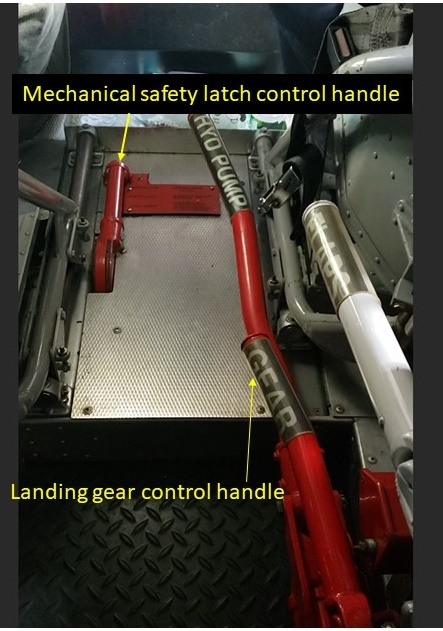
The position of the handles can present ergonomic challenges, as some pilots may need to bend over and/or rotate sideways to reach the handles. When the left-seat pilot is tasked with raising the landing gear, they unlatch the mechanical safety latch control handle by pressing down on the handle with their right hand and pushing the safety latch forward with a finger. Next, the left-seat pilot pulls the handle up. He then rotates inboard at the waist to reach back and lift the landing gear control handle with one hand (the right hand).
The left-seat pilot could use their left hand to steady themselves; however, there is no dedicated handle or recommended position for the left hand to grasp while reaching back with the right hand to lift the landing gear control handle. The pilot may therefore place their left hand near or on the throttle quadrant.
The same process occurs when the right-seat pilot is tasked with raising the gear, except with opposite hands.
1.6.8 Propeller automatic feathering system
The primary role of the propeller automatic feathering system is to quickly reduce the drag associated with a failed engine, with no action required by the flight crew.
The DC3-TP67 is certified under Title 14 of the Code of Federal Regulations (CFR), Part 25: Airworthiness Standards: Transport Category Airplanes, which requires that 2-engine aircraft maintain a climb gradient of 1.2% at the maximum certified take-off weight following an engine failure on takeoff.Footnote 23
The regulations also state that
[t]he airplane configuration may not be changed, except for gear retraction and automatic propeller feathering, and no change in power or thrust that requires action by the pilot may be made until the airplane is 400 feet above the takeoff surface.Footnote 24
The propeller automatic feathering system allows the aircraft to meet obstacle clearance requirements in case an engine fails on takeoff.
A 3-position toggle switch, located on the pilot’s overhead panel, controls the propeller automatic feathering system. The system is also controlled by 2 secondary arming switches located in the throttle quadrant. The secondary arming switches are installed in such a way that they are actuated when the power lever position for each engine corresponds to a power lever angle at which 92% to 94% Ng should be produced.
When the 3-position toggle switch is moved to the ARM position, dual indicator lights on each side of the switch indicate ARMED. The indicator lights indicate READY when each respective system is activated.
When the power levers are set for takeoff power or torque and the 2 secondary arming switches are actuated by power lever position, the READY light illuminates after approximately 5 seconds, indicating that the propeller automatic feathering system is activated.
A torque sensor switch mounted on each engine monitors engine power. When the propeller automatic feathering system is ARMED and indicating READY, the engine-mounted torque sensor will close if engine power decreases below approximately 25% torque. When the torque sensor closes, the activation circuit is completed, which will cause the propeller overspeed governor solenoid to activate, allowing for a drop in oil pressure in the propeller hub. This, in turn, will allow the propeller feathering spring to drive the propeller to the feathered position.
The investigation found that, in colder temperatures, the engines might reach their maximum take-off torque setting before the power levers reach the secondary arming switches in the throttle quadrant. As a result, the READY light never illuminates. This is why some pilots, including the flight crew in this occurrence, do not set the automatic feathering system to ARM. At 16 °C (the temperature at the time of the occurrence flight), the power levers would have reached the secondary arming switches, thus arming the automatic feathering system, if it had been selected to the ARM position.
1.7 Meteorological information
The accident occurred during hours of darkness. Weather information available from the limited weather information systemFootnote 25 at CYPL at 0100 on 21 June was as follows:
- Winds 100° true (T) at 7 knots
- Temperature 16 °C
- Dew point 6 °C
- Altimeter setting 29.96 inches of mercury
The meteorological conditions at the time of the occurrence were not considered to have been a contributing factor in this occurrence.
1.8 Aids to navigation
Not applicable.
1.9 Communications
Not applicable.
1.10 Aerodrome information
The elevation of CYFH is 899 feet above sea level. It has 1 lighted east/west gravel-surfaced runway, Runway 09/27, which is 3497 feet in length. Eabamet Lake is approximately 250 feet to the west of the departure end of Runway 27.
1.11 Flight recorders
The aircraft was equipped with a cockpit voice recorder (CVR) and a flight data recorder (FDR), although neither was required by regulation. At the time of the occurrence, the FDR’s circuit breaker was collared and placarded as unserviceable and had not been operable for more than 2 years.
1.11.1 Cockpit voice recorder
The aircraft was equipped with an L3 CVR model FA 2100, which is capable of recording 120 minutes of high-quality 4-channel audio data. The CVR records the cockpit area microphone, captain’s microphone, first officer’s microphone, and all received transmissions on the aircraft’s selected communication radio, including the intercom.
The data from the CVR were recovered successfully, and the quality of the recording was excellent.
1.11.1.1 Acoustic signature data
A comprehensive analysis was conducted to determine whether information could be derived from the CVR to permit a better understanding of the occurrence flight. The CVR cockpit area microphone channel contained pertinent acoustic data that were essential to conduct a comprehensive analysis.
Five individual flights were captured on the CVR; 4 of those flights, including the occurrence flight, were captured in their entirety. The occurrence flight was approximately 50 seconds, including the moment of impact on the water.
The acoustic environment in the flight deck was evaluated in order to assess whether specific acoustic signatures that were common between the occurrence flight and the previous flights could be identified. These included the isolation and calculation of propeller speeds, the transcription of crew conversation, and the identification of aural alerts and various clicks caused by the movement of engine-related levers and other controls on the flight deck.
The Basler Turbo Conversions STC indicates the nominal take-off propeller speed as 1700 rpm. The 4 recorded takeoffs all showed take-off propeller speeds of approximately 1692 rpm, which confirmed that the propeller speed approximation derived from the audio data was reasonable.
The events of the occurrence flight were examined in detail to compare them with an uneventful departure.
During the 3 normal takeoffs, the same 2 clicks could be detected, followed by the acoustic signature related to the retracting landing gear. The full gear swing time lasted 16.6 seconds and was consistent for each normal takeoff. In each of these 3 flights, no other distinct acoustic events were heard from the point after the gear was commanded up until the crew made the 400-foot call (see Section 1.17.1). The 400-foot call included turning off the automatic propeller feathering system and setting climb power. On the occurrence flight, as the aircraft had not reached 400 feet AGL, no 400-foot call was made.
During the occurrence flight, the acoustic environment of the takeoff commenced in a similar fashion to the previous 3 flights. Once the power was set, the 2 clicks associated with the movement of the landing gear handle were heard. These were followed shortly afterward by the sound related to the landing gear retracting. However, the gear operation was interrupted approximately 1 second after it began. This interruption coincided with 2 additional clicks and a rapid reduction in propeller speed. Impact sounds were heard approximately 17 seconds after the propeller speeds began to decrease.
The source of the clicks heard as the engines were spooling down was investigated, and it was hypothesized that they were a result of the fuel condition levers making contact with the bottom of their slots in the control pedestal as they were moved toward the STOP position.
The acoustic analysis also confirmed that no power or propeller lever adjustments were made before the reduction in engine power on any of the analyzed flights.
To aid the investigation, the TSB created a video to demonstrate how the fuel condition levers could have made this sound. In the video, a TSB investigator manipulated the fuel condition levers while seated in the left seat. The video was filmed with the camera positioned behind and directly between the flight crew seats. In the video, clicks could clearly be heard when the moving levers came into contact with the stationary console. Lateral movements of the levers against the pedestal also produced a discernable sound.
The propeller-speed plots of all the shutdowns heard on the CVR recording and the shutdown observed in the video were compared with each other by amalgamating them into a single plot. Each shutdown was aligned by anchoring the average of the shutdown clicks to a common point in time. To accomplish this, an offset for each shutdown was established that synchronized each average to the same point as the average in the first shutdown. The offsets were then applied to the corresponding propeller-speed curves to establish whether the propeller speeds at shutdown began to decrease coincidentally.
Details of the propeller speed curves for the 4 flights before the occurrence flight, the occurrence flight, and the video of a shutdown filmed on another North Star Air DC3-TP67 were synchronized at the common time point (Figure 4). This plot shows a correlation between the clicks surrounding each engine shutdown and the point at which the propeller speeds begin to decrease. The trend was observable for all normal shutdowns recorded on the CVR, the occurrence flight, and the video of a shutdown filmed on another North Star Air DC3-TP67.
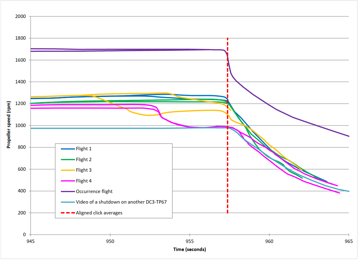
A rapid reduction in propeller speed shortly after liftoff was noted in the occurrence flight. No split in propeller speeds between engines was observed as the propeller speed decreased, suggesting a simultaneous loss of propeller speed on both engines.
The audio recording was also reviewed to determine whether the condition levers were advanced back to the RUN position after the sudden power loss. Although a number of clicks were heard following the abrupt loss in propeller speed, it was not possible to assign these acoustic events to a particular source because there was no reference for comparison.
1.11.2 Flight data recorder
In Canada, section 605.33 of the Canadian Aviation Regulations (CARs) contains the FDR regulations that apply to multi-engine turbine-powered aircraft.
Because the occurrence aircraft was operated under a TC-approved STC that limited the number of passenger seats to 19 or less, an FDR was not required by regulation. However, an FDR had been installed on board but it was deactivated.
The FDR model installed in the aircraft does not record the positions of the power levers, propeller levers, and fuel condition levers; the fuel or oil pressure; or the propeller speed.
1.12 Wreckage and impact information
The aircraft struck the surface of Eabamet Lake in a level pitch, left-wing-low attitude. The aircraft propeller blades were bent but still attached to their respective hubs and to the engines. The wings and tail surfaces remained attached to the fuselage.
Investigators attended the scene while the aircraft was partially submerged and conducted an examination of the aircraft (Figure 5). The leading edge of the left wingtip had crush damage consistent with the left wing striking the water (Figure 6).
A visual inspection of the cockpit, cabin, and engines was limited to areas above the waterline. The cockpit inspection revealed that the inertial separators were in the icing position for takeoff, and that the aircraft ignition and the propeller automatic feathering systems were turned off.
Initial examination of the throttle quadrant (Figure 7) indicated the following:
- The left power lever was in the forward position.
- The right power lever was in the IDLE position.
- The propeller levers were fully forward.
- The left and right engine fuel condition levers were bent and fully forward, but not in the gates.
- Quadrant control friction locks were applied to the engine controls and were in a serviceable condition.
A continuity check of the throttle quadrant controls to their applicable engine control accessories was completed, with no defects found.
The aircraft was recovered from the water on 09 July 2019. On 11 July 2019, investigators returned to CYFH, where the aircraft was parked on the airport ramp. Investigators examined the aircraft, found that all components were accounted for, and were able to confirm flight control continuity.
The engine cowlings were free from debris and did not show signs of air blockage; no intake plugs had been installed.
A visual inspection of the aircraft’s main fuel tanks found that all fuel caps were on. Fuel was found in the main tanks only. Fuel samples were taken from the main tanks and the in-line main fuel filters.
Approximately 545 L of fuel was drained from the left main tank and approximately 550 L from the right main tank. The main fuel tanks did contain a small amount of water; however, no water was found in the in-line main fuel filters.
The left and right fuel shutoff valves were found in the open position, the fuel bypass indicators were not activated, and the fuel cross feed valve was closed.
The engines were removed from the aircraft and sent to Pratt & Whitney Canada. On 16 September 2019, the engines were dismantled to determine whether any mechanical failure had occurred.Footnote 26
The investigation determined that there were no signs of an airframe, engine, or system failure during the occurrence flight.
The operator’s maintenance personnel subsequently replaced the propellers and engines and carried out airframe repairs. The aircraft was then flown to a maintenance repair facility.
1.13 Medical and pathological information
The investigation did not identify anything to indicate that the pilots’ performance was degraded by fatigue or medical factors.
1.14 Fire
There were no signs of a pre- or post-impact fire.
1.15 Survival aspects
1.15.1 Safety belts
The aircraft seats were equipped with safety belts and shoulder harnesses per STC ST302CH’s requirements on the installation of flight crew restraint systems. Footnote 27 The crew restraint system included 1 lap belt and 1 inertia reel shoulder harness attached to each crew member seat.
The layout of cockpit instrument panel switches on the DC3-TP67 may make it difficult for some flight crew members to reach the landing gear controls, especially when shoulder harnesses are used. On the occurrence flight, the flight crew used their lap belts but not their shoulder harnesses. The flight crew did brace for impact and did not receive any injuries.
1.15.1.1 Previous TSB recommendation on the definition of safety belt
The use of a 3- or 4-point restraint system (safety belt and shoulder harness) ensures a more equal distribution of the impact forces and reduces the severity of injuries to the upper body and head.
The TSB has investigated many accidents Footnote 28 involving aircraft that were equipped with detachable shoulder harnesses, in which the TSB determined that the harnesses were not worn at the time of the accident.
Following a helicopter accident at Tweed, Ontario, the TSB investigation determined that the passengers’ shoulder harnesses were not used with the safety belts. Footnote 29 While TC has published various documents in an attempt to clarify the definition of “safety belt” in the regulations, if regulations are not clear in requiring the use of all available components of a safety belt, shoulder harnesses may not be used as intended, increasing the risk of injury or death. Therefore, the Board recommended that
the Department of Transport amend the Canadian Aviation Regulations to remove any ambiguity associated with the definition of “safety belt.”
TSB Recommendation A19-01
In its January 2020 response, TC indicated that it agrees with Recommendation A19-01 and that it had begun assessing the regulatory impact of changing the definition of “safety belt” in subsection 101.1(1) of the CARs. TC had also published guidance material concerning the correct use of safety belts.
In its March 2020 assessment of TC’s response, the Board was encouraged that TC had initiated work to address this safety deficiency. A change in the definition of “safety belt,” when fully implemented, would mitigate the risk associated with the safety deficiency identified in Recommendation A19-01.
Therefore, the response to Recommendation A19-01 was assessed as Satisfactory Intent. Footnote 30
1.16 Tests and research
1.16.1 TSB laboratory reports
The TSB completed the following laboratory reports in support of this investigation:
- LP197/2019 – CVR Download and Analysis
- LP198/2019 – FDR Download
- LP235/2019 – Engine Examination
1.17 Organizational and management information
North Star Air operates under CARs subparts 604, 703, 704, and 705. The company operates the DC3-TP67 aircraft under Subpart 704 (Commuter Operations), as permitted by an authorization issued by TC.Footnote 31
1.17.1 Standard operating procedures
The North Star Air company operations manual details the policies and procedures to be followed by all its operations personnel in the conduct of their duties. North Star Air also issues SOPs to guide its pilots in the operation of company aircraft. The SOPs are specific to each aircraft type and are based on the aircraft’s AFMS. At the time of the occurrence, the SOPs included procedures based on Revision 12 of the AFMS, dated 03 March 2014. However, they did not incorporate changes from the newest revision of the AFMS, Revision 13, dated 10 January 2018.
The SOPs are designed to enhance crew coordination, avoid misunderstandings in flight crew communications, and provide a division of responsibility between the captain and the first officer, and the PNF and the PF.
The SOPs state that, at the “ROTATE” call, the PF shall “confirm the appropriate airspeed on the airspeed indicator” and then “place both hands on the control yoke to indicate understanding has been achieved.” After rotation, the PNF shall state that the aircraft is climbing and call “POSITIVE RATE,” at which point the PF shall confirm the positive climb and call “GEAR UP.” The PNF shall then retract the gears.Footnote 32
The SOPs also state that the initial climb airspeed should be V2.Footnote 33 Once the aircraft climbs through 400 feet AGL “with all indications normal, and take-off power is no longer required,” the PF shall call “CLIMB POWER, AFTER TAKE-OFF CHECK.”Footnote 34 Following this 400-foot call, the PF shall increase airspeed to V2 + 10 knots and the PNF shall reduce engine power to 95% torque and 1700 rpm, and then initiate the after-takeoff checklist.Footnote 35
No SOPs require power or propeller lever adjustments after the take-off power is set until the aircraft is at 400 feet AGL.
1.17.2 Checklists
Checklists guide pilot actions during normal, abnormal, and emergency operations. They are designed to ensure that steps are followed in a specific order and without omission. However, checklists do not guarantee a fail-safe operation. To be effective, checklists must be specific and unambiguous, and pilots must be trained on their proper use.
Some checklists are published in aircraft documents, such as the pilot’s operating handbook or the approved aircraft flight manual. In addition, air operators typically produce their own checklist procedures in their SOPs or quick reference handbook.
North Star Air’s SOPs state that “the aircraft checklists shall be used at all times.”Footnote 36 The SOPs for the occurrence aircraft indicate that “[a]ll checks and drills once initiated shall be carried out in the sequence that they are listed until complete. No items may be deleted nor the order altered.”Footnote 37 TSB investigators found copies of checklists and a quick reference handbook in the cockpit following the occurrence.
On the occurrence flight, the flight crew used the following before-takeoff checklist in accordance with the SOPs:
BEFORE TAKEOFF CHECK
FIRST OFFICER
CAPTAIN
Trims
Set
Flaps
Up
Controls
Checked
Flight Instruments
Checked
The flight instruments shall
be checked for appropriate
operation during turns of at
least 45 degrees. The Turn
Coordinator (or Needle & Ball),
HSI [horizontal situation indicator],
RMI [radio magnetic indicator] and
Compass should be checked for
proper operation.
Radios
Set
Departure Briefing
Complete
Autofeather
Armed
Standby Fuel Pumps
ON
Cabin Secure
Check
Transponder
ON
Headings
Checked/Set
Strobe Lights
ON
Turning the strobe lights on
should be delayed until takeoff
clearance is received.
Landing Lights
ON
Tail Wheel
Locked
Ensure the aircraft is lined up
prior to locking the tail wheel. Footnote 38
On 10 January 2018, Revision 13 of the AFMS was approved by the FAA. On 16 March 2018, Basler Turbo Conversions notified North Star Air via email that a new revision of the AFMS had been approved, and provided instructions and documents for North Star Air to amend its AFMS by removing and replacing the appropriate sections. Revision 13 included an update to “Chapter 3: Normal Procedures,” indicating that both left and right ignition switches should be set to CONT for takeoff and landing. Footnote 39 On 26 March 2018, North Star Air acknowledged receipt of Revision 13 to Basler Turbo Conversions, but it did not incorporate the revision into the AFMS.
Therefore, at the time of the accident, the SOPs did not contain guidance for pilots to set the ignition switches to CONT for takeoff, nor did they provide a procedure for doing this.
1.18 Additional information
Not applicable.
1.19 Useful or effective investigation techniques
Not applicable.
2.0 Analysis
2.1 General
The investigation determined that there were no signs of an airframe, engine, or system failure during the occurrence flight.
The simultaneous engine shutdown led investigators to consider inadvertent engine control inputs as a possible cause. The analysis will therefore focus on the acoustic signatures from the occurrence flight and the 4 previous flights, the location of the landing gear handles, and the operator’s procedures for updating checklists.
The analysis will also examine the possibility of engine relights, the design and ergonomics of the throttle quadrant, and the use of the propeller automatic feathering system.
Finally, the analysis will discuss the use of safety belts.
2.2 Acoustic signature analysis
The cockpit voice recorder (CVR) recorded the 4 flights before the occurrence flight. The sound of a rapid reduction in propeller speeds shortly after takeoff was heard only on the occurrence flight. Propeller speed was reduced at the same time and at the same rate on both engines. A power loss on 2 engines can occur; however, the shutdown is usually staggered in sequence, with 1 engine reducing power before the 2nd engine. Clicks were heard immediately before the reduction in propeller speed, which likely indicated that the fuel condition levers made contact with the control pedestal as they were moved toward the down position (STOP).
The analysis of the acoustic signatures found that the timing of the clicks heard during the normal engine shutdowns corresponded to an immediate reduction in propeller speed. This phenomenon was also observed in a video of a shutdown filmed on another DC3-TP67 operated by North Star Air Ltd. (North Star Air).
During the uneventful departures, the acoustic signatures did not include clicks between when the gear was commanded UP and when the 400-foot call was completed.
On the occurrence flight, acoustic signatures related to the movement of gear handles and the activation of the hydraulic system indicate the gear was selected UP. However, the gear operation was interrupted approximately 1 second after it began due to a loss of hydraulic pressure. This interruption coincided with 2 clicks and a rapid reduction in propeller speed.
The rapid reduction in propeller speeds and the sound of the 2 clicks suggest that the fuel condition levers were likely accidentally moved, cutting the fuel to both engines simultaneously. However, the investigation could not find an acoustic signature to indicate conclusively whether the levers had been returned to the RUN position. There were no power or propeller lever adjustments made before the reduction in engine power.
2.3 Landing gear handles
The location of the landing gear controls on the DC3-TP67 can present ergonomic challenges for some pilots.
In the occurrence aircraft type, the pilot raising the landing gear needs to bend over and/or rotate sideways to reach the mechanical safety latch control and landing gear control handles, and then must lift the landing gear control handle with one hand. Because there is no dedicated position or handle for pilots to place the opposite hand to steady themselves if necessary, such as during the initial climb out, there is an increased likelihood that the pilot will place that hand on the throttle quadrant and will move a control by accident.
2.4 Throttle quadrant design and ergonomics
Controls and displays are designed and laid out with the aim of balancing functionality, effectiveness, usability, and safety. The layout of the controls in the cockpit takes into account importance, frequency and sequence of use, and grouping by function.
There are ways to protect controls from being moved unintentionally, such as gates, friction locks, or locking mechanisms. On the occurrence aircraft, gates are used to secure the fuel condition levers in the RUN position. The gates are narrow and the fuel condition levers are long, making it possible to snag or bump the fuel condition levers out to the left and down. The levers travel out of the gates in the same direction, making it possible to move both fuel condition levers with one hand.
There are trade-offs between measures to prevent unintentional movement and usability, because such measures may make controls more difficult to operate.
Cockpit discipline and procedures also reduce the risk of unintentional movement. Cockpit design uses varied colours, sizes, and shapes to facilitate visual and tactile identification. A colour and shape coding and grouping for these levers is common in the industry.
The acoustic signature analysis indicated the simultaneous loss of power to both engines, suggesting that the fuel condition levers were accidentally moved to the STOP position shortly after the gear selection.
During the climb out, both of the pilot flying’s (PF’s) hands were likely on the yoke, in accordance with standard operating procedures (SOPs). The pilot not flying (PNF) had his right hand on the landing gear control handle, and his left hand and arm may have rotated toward the throttle quadrant. After the PNF raised the landing gear control handle with his right hand, he may have accidentally moved the fuel condition levers while rotating back into position and steadying or bracing himself with his left hand. Therefore, after lifting the landing gear control handle, with his left hand on or near the throttle quadrant, the PNF may have inadvertently moved the fuel condition levers, cutting the fuel to both engines simultaneously.
The design of the levers in the throttle quadrant of the occurrence aircraft is consistent with ergonomic guidelines to prevent accidental movement: the design provides tactile and visual cues, movement resistance, and dual-axis motion, which are safeguards against accidental movement. However, the fuel condition levers are still usable in the case of an emergency when an engine shutdown is necessary.
2.5 Checklist updates
The crew followed the before-takeoff checklist, which did not include setting the ignition switches to CONT (continuous mode) for takeoff, although this step was required by the latest revision of the airplane flight manual supplement (AFMS), dated 10 January 2018.
The company received a notification of the updated AFMS on 16 March 2018. The notification included instructions on which sections of the manual to remove and replace. The investigation did not determine why the updated procedure was not incorporated into the North Star Air before-takeoff checklist.
If operators do not follow manufacturers’ directions to amend procedures, operators will use incorrect operating procedures, increasing the risk of compromising safety margins.
2.6 Relighting engines in flight
Relighting an engine that has flamed out in flight, due to a momentary disruption of airflow or fuel to the engine, should be automatic when the ignition system switches are in the CONT position. If the ignition system switches are not set to CONT, as was the case in the occurrence flight, the flight crew are required to complete an in-flight engine relighting procedure.
In-flight engine relighting procedures are approved emergency procedures published in the North Star Air SOPs. These procedures (propeller windmilling and starter assisted) require flight crews to follow a checklist.
In the propeller windmilling procedure, a minimum airspeed of 160 knots is required to successfully relight an engine in flight. The SOPs state that the initial climb after takeoff and up to 400 feet above ground level should be conducted at an airspeed of V2 (approximately 90 knots), which is lower than the 160 knots required for the propeller windmilling procedure. The crew would have needed to increase airspeed by descending, but the aircraft had insufficient altitude to attain the required airspeed at the time of the engine power loss. Therefore, the starter-assisted relight procedure was the only option available to restore engine power at this altitude and airspeed.
The SOPs indicate that, when following the starter-assisted relight procedure, the engine should normally relight within 10 seconds from when the fuel condition lever is moved to the RUN position, and that the relighting would be evident from a rise in gas generator speed (Ng). Only 17 seconds elapsed from the time the engines lost power until impact. Therefore, the flight crew did not have enough time to attempt this engine relight procedure before the aircraft collided with the water surface.
In this occurrence, it could not be determined whether a successful relight would have occurred if the ignition system switches had been set to CONT and if the fuel conditions levers had been returned to the RUN position when the crew recognized the engine power loss. Engine relights with ignition system set to CONT may be possible if the Ng is above 10%. The Ng percentage when the crew recognized the engine power loss could not be determined, but it was likely below 10%, which would have prevented engine restart.
Due to insufficient altitude and time available to the crew, none of the 3 engine relight options were available to the flight crew before the aircraft collided with the water surface.
2.7 Propeller automatic feathering system
The before-takeoff checklist requires that the automatic feathering system be armed for takeoff; however, there were times when the engines would reach the torque setting before the power levers reached the arming switches.
The primary role of the propeller automatic feathering system is to quickly reduce the drag associated with a failed engine, without requiring flight crew action. When the aircraft was certified, it had to meet the minimum climb gradient on departure, following an engine failure, to ensure obstacle clearance requirements. The DC3-TP67 certification was done with the automatic feathering system activated for takeoff. In this occurrence, the crew did not arm the automatic feathering system; therefore, it would not have been available if it had been required.
If the propeller automatic feathering system is not armed, there is a risk that, in the event of an engine failure, the aircraft would not be able to maintain the required climb gradient and obstacle clearance would not be guaranteed.
2.8 Safety belts
The use of inertia reel shoulder harnesses ensures a more equal distribution of the impact forces. Wearing a lap belt and a shoulder harness is known to reduce the severity of injuries to the upper body in the event of an accident, compared with wearing only the lap belt. The shoulder harness should allow for some freedom of movement, to reduce the likelihood that pilots will unfasten it during flight.
However, on this aircraft type, the layout of the cockpit instrument panel switches and the location of controls (such as the landing gear handle) can make it difficult for pilots to reach them while wearing a shoulder harness. Nevertheless, if pilots do not use available shoulder harnesses, there is an increased risk of injury in the event of an accident.
3.0 Findings
3.1 Findings as to causes and contributing factors
These are conditions, acts or safety deficiencies that were found to have caused or contributed to this occurrence.
- After lifting the landing gear control handle, with his left hand on or near the throttle quadrant, the pilot not flying may have inadvertently moved the fuel condition levers, cutting the fuel to both engines simultaneously.
3.2 Findings as to risk
These are conditions, unsafe acts or safety deficiencies that were found not to be a factor in this occurrence but could have adverse consequences in future occurrences.
- If the propeller automatic feathering system is not armed, there is a risk that, in the event of an engine failure, the aircraft would not be able to maintain the required climb gradient and obstacle clearance would not be guaranteed.
- If operators do not follow manufacturers’ directions to amend procedures, operators will use incorrect operating procedures, increasing the risk of compromising safety margins.
- If pilots do not use available shoulder harnesses, there is an increased risk of injury in the event of an accident.
3.3 Other findings
These items could enhance safety, resolve an issue of controversy, or provide a data point for future safety studies.
- Due to insufficient altitude and time available to the crew, none of the 3 engine relight options were available to the flight crew before the aircraft collided with the water surface.
4.0 Safety action
4.1 Safety action taken
The Board is not aware of any safety action taken following this occurrence.
This report concludes the Transportation Safety Board of Canada’s investigation into this occurrence. The Board authorized the release of this report on . It was officially released on .