Main-track derailment
Canadian National Railway Company
Freight train A45851-29
Mile 96.38, Grande Cache Subdivision
near Grande Cache, Alberta
The Transportation Safety Board of Canada (TSB) investigated this occurrence for the purpose of advancing transportation safety. It is not the function of the Board to assign fault or determine civil or criminal liability. This report is not created for use in the context of legal, disciplinary or other proceedings. See Ownership and use of content. Masculine pronouns and position titles may be used to signify all genders to comply with the Canadian Transportation Accident Investigation and Safety Board Act (S.C. 1989, c. 3).
Summary
On 29 October 2016, at approximately 1953 Mountain Daylight Time, northbound Canadian National Railway Company freight train A45851-29, travelling at 27 mph, derailed 28 cars in a right-hand curve at Mile 96.38 of the Grande Cache Subdivision. The derailed cars were covered hopper cars loaded with frac sand. The derailment damaged about 1300 feet of track. There were no injuries.
Le présent rapport est également disponible en français.
1.0 Factual information
1.1 The accident
On 29 October 2016, the Canadian National Railway Company (CN) occurrence train crew, consisting of a locomotive engineer (LE) and a conductor, was ordered out of Winniandy, Alberta, for 0620.Footnote 1 The crew members put train A459 together and departed southbound for Swan Landing, near Grande Prairie, Alberta, at 0730. Upon arrival at Swan Landing at 1230, the crew yarded train A459, and then prepared northbound train A45851-29 (the train) for immediate departure.
The train was configured with distributed power (DP). Three locomotives were positioned at the head end, and 2 locomotives were positioned at the tail end. The train, which was transporting 102 loaded cars of Northern White frac sand,Footnote 2 weighed 14 586 tons and was 4652 feet long. The frac sand had originated at Weyerhaeuser, Wisconsin, United States, and was destined for Wembley, Alberta, through Duluth, Minnesota; Winnipeg, Manitoba; Edmonton, Alberta; and Swan Landing.
The train departed Swan Landing at 1530 and travelled northward over the Grande Cache Subdivision.
At about 1953, while proceeding at 27 mph on a descending grade through a 6° right-hand (RH) curve, a train-initiated emergency brake application occurred. Neither crew member had seen or heard anything unusual prior to the brake application. At that time, the head end of the train was located at Mile 96.43, approximately 23 miles north of the Grey siding (Figure 1).

The train crew followed the emergency procedures, including making the necessary radio broadcast and calling the rail traffic controller. After the train came to rest, the conductor walked back to inspect it. The conductor noted that there had been a separation between the 1st car and 2nd car but did not observe the derailed wheel sets of the 2nd and 3rd locomotives. Observing that the 1st car behind the head-end locomotives had not derailed, the conductor closed the angle cock on the car. In the darkness, the conductor did not see the rest of the train and assumed that the train had only broken a knuckle, resulting in the separation.
The train crew decided to back up the locomotives and the car to connect to the separated portion of the train. After reversing 179 feet, the crew members noted that there had been a derailment. At the time of the occurrence, the temperature was −3 °C.
1.2 Site examination
The lead locomotive did not derail. The leading wheel sets of the trailing trucks (i.e. the No. 4 axles in the direction of travel) of the 2nd and 3rd locomotivesFootnote 3 both derailed. The R3 wheels were derailed to the outside of the high rail, and the L3 wheels were derailed to the inside of the low rail.
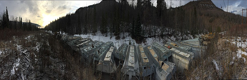
The first car (CEFX 312560) behind the head-end locomotives remained coupled and was not derailed. The 2nd to the 29th cars derailed. The 2nd and 3rd cars derailed to the high side of the curve and were on their sides. The 4th to 26th cars were in a jackknifed position across the rails (Figure 2). The 27th, 28th, and 29th cars were derailed upright on the grade.
There were no marks on the ties from the derailed R3 locomotive wheels; however, there were marks on the base of the low rail and a rail break between the point where the locomotives initially stopped and the point where it stopped after reversing.
1.3 Train information
The train was powered by 5 General Electric (GE) ET44AC locomotives with 3 positioned on the head end and 2 positioned on the tail end (Table 1 and Table 2).
| Locomotive number | Power status | Dynamic brake status |
|---|---|---|
| CN 3057 | On line | Enabled |
| CN 3066 | On line | Enabled |
| CN 3094 | On line | Disabled |
| Locomotive number | Power status | Dynamic brake status |
|---|---|---|
| CN 3103 | On line | Enabled |
| CN 3045 | On line | Enabled |
All 5 locomotives were in serviceable condition with no outstanding maintenance issues.
Specifications and dimensions of GE ET44AC locomotives include the following:
- GE HiAd™, 3-axle, tandem motor, bolster-less, low-weight transfer trucks. Standard centre axle lateral clearance is 1.25 inch when new with a condemning limit of 1.75 inch (to ease curving). Truck wheelbase is nominally 13 feet 2 inches.
- The length between the front and rear coupler pulling faces is nominally 73 feet 8.26 inches.
- The weight is 427 500 pounds.
The loaded frac sand cars had been inspected and had travelled over a number of wayside detectors in the 2 days before the occurrence.
On 27 October 2016, a certified car inspection (CCI) and a No. 1 air brake test were conducted at Symington Yard in Winnipeg. No equipment defects or anomalies were noted.
On the day of the occurrence, at Stony Plain, Alberta (Mile 23.8 of the Edson Subdivision), car CEFX 311415 (69th car on the train) activated the alarm on the wheel impact load detector with a peak reading of 90.3 kipsFootnote 4 on the R1 axle. This car was placed into a "Preventative maintenance – safe to move" status by CN. The notation ** W4 WHEEL IMPACT STRIKE ** was added to the train journal. This notation was to stay on the train journal until the wheel was changed at the next CCI location.
On the day of the occurrence, the train passed hot box detectors at Mile 38.94 and Mile 89.7 of the Grande Cache Subdivision. No alarms were activated at either of these detectors.
Each car in the unit train had been evenly loaded, and weighed about 142 tons (Figure 3).

1.4 Equipment information
All 102 cars of the train were 42-foot covered hopper cars (Figure 4) designed for hauling heavy, dense loads. The gross weight of each car was 286 000 pounds, with a load limit of 232 800 pounds. These cars are shorter than grain and coal hopper cars. However, when loaded with frac sand, these cars normally carry about the same load as the longer grain and coal hopper cars.

Longitudinal forces are not transformed into higher lateral forces on cars in the alignment position (i.e., on tangent track). However, for cars of the same weight, in some circumstances, shorter cars might exert higher forces on the rail in curves (i.e., unbalanced centrifugal L/V and/or transformed lateral forces in jackknifed position under buff in-train force) than longer cars.Footnote 5Footnote 6
In this occurrence, the unit train of frac sand weighed 14 586 tons over 4652 feet, which is equivalent to 3.1 tons/foot of train length. Grain trains are typically operated at about 2.0 tons/foot of train length.
1.4.1 Vehicle dynamics of a 42-foot covered hopper car
The Transportation Technology Center, Inc. (TTCI) has investigated the effects of heavy axle load traffic on infrastructure, specifically relating to minimum length interchange cars (i.e., shorter cars).Footnote 7 Testing at the Facility for Accelerated Service Testing (FAST) was conducted to determine the differences in vehicle dynamics of a 42-foot (short) car compared to a 53-foot (standard length) car (e.g., coal gondola or open-top hopper). TTCI developed NUCARS® simulation models based on car body characterization and resonance tests and validated the models using instrumented wheel set data from the test at the FAST.
In addition, simulations by the Association of American Railroads on a generalized short hopper car model were conducted with track geometry inputs representative of United States Federal Railroad Administration Class 2, Class 3, and Class 4 tracks.Footnote 8
The key relevant findings of these studies include the following:
- Short cars perform similarly to standard length cars in terms of wheel-rail forces, provided the same trucks are used for both car types.Footnote 9
- Loadings applied to the track are distributed through the ballast and subgrade and can be defined by a series of pressure bulbs within the subgrade.Footnote 10
- Since there is no dimensional difference between the trucks of long and short cars at the car-to-car interface (i.e., between subsequent cars), the pressure distribution under each set of trucks is expected to be identical. However, the shorter distance between sets of trucks in short cars will bring the pressure bulbs produced by each set of trucks closer together and create a larger area of overlapping pressures. Overlapping lateral forces are also created.Footnote 11
1.5 Recorded information
The data from the locomotive event recorder was reviewed to determine how the train was handled on the descending grade between Grey (Mile 73.0) and the point of derailment (POD) (Mile 96.38). The train speed ranged between 23 mph and 29 mph, exceeding the maximum speed of 25 mph (Figure 5). The dynamic brake (DB) was placed in position 6 and position 7 several times, exceeding the limit of DB5 (Figure 5).Footnote 12

Table 3 provides a summary of train handling events before and during the derailment.
| Time | Location (Mile) | Event |
|---|---|---|
| 1952:36 | 96.06 | The train was travelling at 28 mph, with dynamic brake in DB4. |
| 1952:43 | 96.11 | The dynamic brake was increased to DB5. |
| 1952:56 | 96.22 | The dynamic brake was decreased to DB4. |
| 1953:00 | 96.25 | The dynamic brake was increased to DB6. |
| 1953:03 | 96.27 | The train entered the start of a 6° curve. |
| 1953:22 | 96.42 | With the train travelling at 27 mph, the dynamic brake was decreased to DB5. |
| 1953:23 | 96.43 | The train experienced a train-initiated emergency brake application. |
| Between 1953:23 and 1953:46 | 96.50 | The locomotives and first car separated from the train and came to a stop* after travelling 386 feet in emergency. |
| 2007:53 | 96.50 | The locomotives and first car were reversed. |
| 2009:26 | 96.47 | After reversing for 179 feet, the locomotives and first car were stopped. |
* During stopping, the train was in DB only, as no air brakes were applied.
1.6 Subdivision information
The Grande Cache Subdivision extends northward from Swan Landing (Mile 199.4 of the Edson Subdivision) to Grande Prairie (Mile 232.9). Train movements are controlled by the occupancy control system (OCS) as authorized by the Canadian Rail Operating Rules, and supervised by a rail traffic controller located in Edmonton.
Prior to 2009, the track between Mile 0.0 and Mile 112.0 was upgraded to handle heavier traffic (up to 286 000 pounds loading).
In the vicinity of the occurrence, the maximum speed was 25 mph, making it Class 2 track according to the Transport Canada (TC)–approved Rules Respecting Track Safety, which is also referred to as the Track Safety Rules (TSR).
Until June 2014, loaded cars of coal, grain, and wood product were transported south, and the empty cars were transported north. In addition, an occasional northbound loaded thermal coal train would go to a power plant near Winniandy. In June 2014, unit trains transporting frac sand began operations northward on this subdivision, substantially increasing the traffic and tonnage (Table 4). The coal mine at Winniandy closed in December 2015, and the last southbound coal trains ran in October 2016. Grain and wood products from Grande Prairie continued to be hauled south. In 2016, train traffic consisted of about 2 trains per day, totalling about 11.6 million gross ton miles for the year.
| Year | Date range | Total gross ton miles | Average daily train movements |
|---|---|---|---|
| 2013 | 2013-10-01 to 2013-12-31 | 471 135 430 | 3 |
| 2014 | 2014-01-01 to 2014-12-31 | 1 982 858 871 | 4 |
| 2015 | 2015-01-01 to 2015-12-31 | 1 733 420 770 | 3 |
| 2016 | 2016-01-01 to 2016-10-31 | 1 157 245 362 | 2 |
Since the early 1970s, CN had been using SD40 locomotives (i.e., six-axle, 3000-horsepower (HP) diesel locomotives built by General Motors Electro-Motive Division) for coal and grain unit train operations on the Grande Cache Subdivision. In the mid to late 1980s, six-axle locomotives of 3600 HP and 3800 HP were introduced. Through the 1990s, there was a gradual introduction of 4000 HP, 4300 HP and 4400 HP six-axle locomotives. Between 1999 and 2006, while the line was operated by another railway, six-axle locomotives rated between 3000 HP and 3900 HP were used.
After the line was reacquired by CN in 2006, the latest-technology locomotives (i.e., heavyweight [420 000 pounds] and high horsepower [4300 HP, 4400 HP]) resumed operation to facilitate the movement of heavy bulk (coal, grain) and manifest traffic. In 2013, when the AC locomotives arrived, CN had at least six years of experience operating heavyweight, high horsepower DC locomotives in both conventional and distributed power configurations on the Grande Cache Subdivision. At the time of the occurrence, CN had been expanding the use of AC locomotives across its network as more of these locomotives were delivered.Footnote 13
1.7 Track information
In the vicinity of the occurrence, there was a 6° RH curve on a long descending grade of between 0.76% and 0.84%. The track in the area of the derailment was in a cut area of shale rock, with a culvert draining to the west and both ditches draining to the north. The track was constructed mostly of No. 2 hardwood ties. In June 2016, every 2nd to 4th tie had been replaced and the track had been re-surfaced.
The spiking pattern was mostly 3 spikes per tie plate (2 gauge spikes and 1 field spike) with some "B" pattern (2 gauge spikes and 2 field spikes) using 14-inch double-shouldered tie plates. The rails were fully anchored using fair anchors on the high side and all-new bar stock style anchors on the low side. The anchors were generally tight to the ties. The ballast was crushed rock, with 14- to 16-inch shoulders.
The high rail in the curve was 1991 Algoma 115-pound continuous welded rail (CWR), with about 7 mm of head wear and 8 mm of flange wear. Between 2014 and 2016, accelerated rail wear had been noted in the curve high rail. The low rail was new 2016 EVRAZ 115-pound CWR that had been installed in September 2016. After the low rail was replaced with a new, full-height rail, the average superelevation on the curve was reduced by 0.42 inch to 0.99 inch.
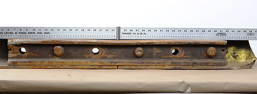
A 34-foot plug rail (1987 Sydney) had been previously installed in the high rail near Mile 96.38. Prior to the occurrence, both joints for the plug rail were reported to be fully bolted. Following the occurrence, both joints were intact, but the nuts (on the gauge side) for 3 bolts had been sheared off on each joint (Figure 6). The plug rail was also broken near the south joint.
The gauge joint bars showed wheel flange contact. The rail head wear on the high rail was 7 mm, which was 1 mm less than the limit of 8 mm specified in the CN Engineering Track Standards (ETS) before high clearance joint bars are required.
Flange rail lubricators were located at Mile 96.2 and Mile 100.1.
The plug rail pieces, including the 2 joints, were sent to the TSB Engineering Laboratory for detailed examination.
1.7.1 Track inspection and maintenance
In 2016, the Grande Cache Subdivision had been ultrasonically tested 11 times. During the most recent rail flaw detection test on 21 October 2016, no internal rail defects were identified in the vicinity of the POD.
However, during a previous test on 15 August 2014, a 4 mm rail end batter (REB) condition had been identifiedFootnote 14 in the south joint. This REB condition was being measured and monitored as required by CN's track standards.Footnote 15 The CN standard is to replace the rail within 7 days if the REB is greater than 5 mm.
The track was last inspected by hi-rail on 28 October 2016. No defects were noted in the vicinity of the occurrence.
The most recent track geometry test was conducted on 12 September 2016. No geometry defects were noted in the derailment curve during this test, which was 2 days after the low rail installation. In the vicinity of the derailment, the cantFootnote 16 in the high rail was measured to be between 0.43° and 0.77°. For the low rail, the cant was measured to be between 1.24° and 1.43°. The gauge through the curve varied between 0.14 inch and 0.37 inch wide, which is considered by the railway as "non-actionable."
Following the tie installation in June 2016 and the low rail change-out in September 2016, re-spiking and gauging the curve had corrected gauge defects that had been identified during a geometry test conducted on 27 May 2016. In addition, the securement of the low rail was strengthened due to the increased spiking and gluing of the spike holes during the change-out.
1.7.2 Rail securement
Various types of rail fastening systems can be used in curves, such as spikes, elastic fastening systems, and screw fasteners.
Spikes position the rail in the tie plate and secure the tie plate to the tie to maintain gauge. Spikes are mainly designed to restrain rail lateral movement; they provide little to no restraint for rail vertical movement and roll.
Elastic fastening systems provide a much stronger track structure that is more resistant to high lateral and longitudinal forces and to the development of wide gauge and rail cant, which can result in tie damage. Elastic fasteners also provide increased rail hold-down strength, which increases resistance to rail rollover.
Screw fasteners provide increased resistance to tie plate movement, thereby increasing gauge widening strength and the gauge widening life of the track. This reduces "spike kill" caused when fasteners are removed and reapplied during rail change-outs.
Under adverse vehicle and wheel conditions, spikes do not provide sufficient and sustainable restraint against rail rollover on curves. On moderate curves ranging between 6° and 8°, and more severe curves greater than 8°, the use of elastic fasteners would be highly beneficial if heavy loaded unit trains operate over the territory.
The TSB has conducted several investigationsFootnote 17 where differential rail securement within a curve was determined to be a contributing factor to derailments. In these occurrences, the high rail had been stiffened by increased spiking or the installation of elastic fasteners, which increased the rail's resistance to dynamic wide gauge lateral forces. However, without a similar increase for the low rail, lateral forces from passing trains acted on the relatively weaker low rail, leading to fastener deterioration, low rail reverse cant, wheel drop-in, and derailment.
A similar situation can develop when the low rail is changed and the high rail is not. Replacing only the low rail can result in differential rail securement with lateral forces from passing trains acting on the relatively weaker high rail, leading to accelerated fastener deterioration, high rail reverse cant, increased potential for wheel drop-in, and derailment.
1.8 Curve superelevation
The derailment occurred in a 6° RH curve on a long 0.84% to 0.76% descending grade. A track geometry car test was performed on this curve on 12 September 2016. The test revealed the following characteristics of this curve:
- The length of the curve was 1762 feet.
- The curve extended from Mile 96.24 to Mile 96.57.
- The average degree of curvature was about 6° (ranging from 5.94° to 6.06°).
- The superelevation ranged from 0.51 inch to 1.28 inches.
- The average superelevation was 0.99 inch.
- The design speed was 26.7 mph.Footnote 18
- The balanced superelevation was 2.75 inches.
- All gauge defects were less than 0.5 inch.
When a train negotiates a curve, it is desirable for the locomotives and cars to tilt inward toward the centre of the curve. This tilt can be achieved by elevating the high rail. If all trains were to operate at the same speed through the curve, the ideal condition for smooth riding and for minimum rail wear would be to elevate the high rail so that, at that speed, known as the equilibrium speed, the centrifugal force on the high rail and the low rail are equal. This condition is known as balanced superelevation.
However, because there will normally be different types of traffic travelling at different speeds, trains negotiating a curve more slowly than the equilibrium speed will result in higher-than-normal wear on the low rail. Conversely, trains travelling faster than the equilibrium speed will result in higher-than-normal wear on the high rail. The mix of traffic and train speed on a rail line are factors to consider when determining the superelevation of the curve.
For many years, the Grande Cache Subdivision primarily handled loaded cars southbound and empty cars northbound. Accordingly, the curves had been elevated for the loaded, slower-moving southbound trains ascending the 1% (nominal) grade between Winniandy and Grey. With the introduction of loaded northbound frac sand trains, accelerated rail wear had been occurring on the high rail through the curves.
The CN standard for curve superelevation (Recommended Method 1305) specifies (in part):
The maximum superelevation that can be applied on a curve has to be the balanced superelevation or 5 inches, whichever is less.
The minimum superelevation that can be applied on a curve shall be the greater of ½ inch, 2 inches below the balanced elevation for freight timetable speed, 3 inches below the balanced elevation for passenger timetable speed, or 6 inches below the balanced elevation for LRC (Light Rapid Comfortable) timetable speed. The elevation can be anywhere within this range.
In 2015, CN conducted an internal study of actual train speeds on curves. The objective of the study was to reset superelevations to better match the speeds at which the majority of trains (i.e., 95th percentile) were actually operating within the curve. Based on this study, CN produced a curve list with desired superelevations for individual curves. During any future surfacing or program work, the superelevations within each curve could then be reset.
A curve with a new high rail and a fully worn low rail designed for 2-inch imbalance may have more superelevation than the design of the curve. This would result in the maximum allowable speed or design speed (Vmax) on the curve being increased close to the Vmax limit for 3-inch imbalance. The calculation for Vmax is specified in the TSR, Part II, Subpart C, Section 4.2.Footnote 19 When the low rail is changed, the curve superelevation would then be brought back closer to the Vmax limit for 2-inch imbalance. Vmax defects requiring a reduction in train speed to match the actual superelevation of the curve are detectable by the track geometry car.
As part of the 2015 study, CN compared its 2-inch imbalance policy (i.e., 2 inches below the balanced elevation for freight timetable speed) against other Class I railways and determined that 2 inches was among the highest imbalances allowed by this class of railway. As a result, CN determined that a flat 2-inch imbalance policy would not always be the preferred approach.Footnote 20 Instead, a 1-inch imbalance was to be considered. If the curve was set for 1-inch imbalance, its superelevation would be brought closer to balanced superelevation, Vmax would be lowered, and rail wear would be reduced.
In this occurrence, the 6° curve had an average superelevation of 0.99 inch, an equilibrium speed of 15.4 mph, and a design speed (Vmax) of 21.8 mph (based on a 1-inch imbalance) or 26.7 mph (based on a 2-inch imbalance).
There is an exponential relationship between balanced superelevation and speed. To operate at 27 mph, a 6° curve requires a superelevation of 2.06 inches (based on a 1-inch imbalance) or 1.06 inches (based on a 2-inch imbalance).
1.9 Lateral and vertical forces at the wheel/rail interface
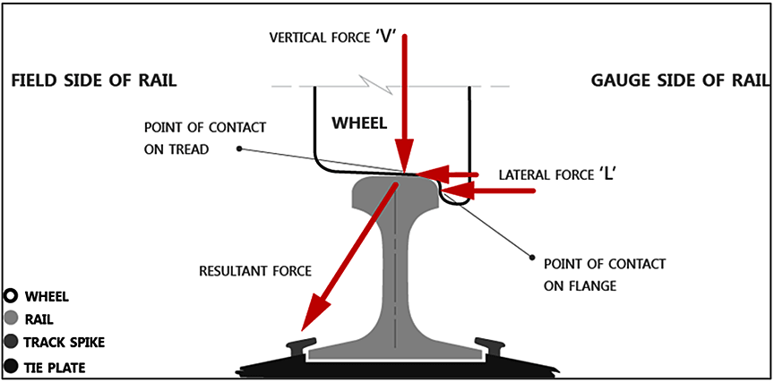
A combination of lateral (L) and vertical (V) forces exist at the wheel/rail contact (Figure 7). The ratio of lateral-to-vertical (L/V) forces indicates the probability of a derailment: the probability of a derailment increases as the L/V ratio increases.
When a train is in compression or buff state, particularly in a jackknifed position in a curve, the drawbar angle can reach its maximum with the couplers pushing against the side of the housing. Longitudinal forces can be transformed into large lateral forces that can have an impact on the truck and be transmitted to the wheel flange on the high rail, canting and even rolling the rail over when the resultant force acts beyond the outer edge of the rail base. A high lateral force combined with a low vertical force (e.g., if the train has empty cars) can tend to push the wheel flange up and over the gauge face of the rail (wheel climb).
The tendency for wheel climb is related to the wheel flange angle, the coefficient of friction (significant creep or slipping at the wheel/rail contact area) and the angle of attack of the leading wheel set with reference to the rail as it is forced around a curve. Wheel climb is associated with large lateral forces and reduced vertical force. The potential for wheel climb occurs when the L/V ratio exceeds 0.80. Wheel climb on the high rail occurs when the flange contacts the gauge face and the L/V ratio is high, normally due to a high lateral force or lowered vertical force due to wheel unloading that may be caused by buff forces on a heavy train descending a steep grade.
For rail rollover with a loaded car, the L/V threshold is 0.65 for well-maintained track.Footnote 21
1.9.1 Situations affecting lateral and vertical forces in curves
When there is wear on the gauge face of the high rail, 2-point contact between the wheel and the rail (one contact on the wheel tread and the other on the flange) may occur when flanging around the curve, lowering the L/V threshold for wheel climb or rail rollover. For rail rollover, worn rail and worn hollow-tread wheels is the worst combination.
The wheel flanges, centrifugal forces, and frictional curving forces of wheel truck assemblies will exert lateral force on the high and low rails. In-train forces (buff and draft forces) can also exert lateral force on the track, especially in curves.
As lateral forces try to tip the rail over, the rail is restrained by its torsional stiffness and by the weight on adjacent wheels. Raising the high rail (superelevation) compensates for centrifugal force by shifting some car weight to the low rail, reducing the lateral (centrifugal) force and the vertical force on the high rail. Lateral force increases in curves with under-balanced superelevation.
Lubricating the top of the low railFootnote 22 will reduce frictional curving forces that may cause high rail rollover or wheel drop-in on the low rail. Lubricating the flange of the high rail will reduce wear, frictional creep (slipping), and curving forces, reducing the potential for wheel climb.
For a wheel to drop in, there must be either a significant increase in lateral load on the track or a significant reduction in lateral strength of the track.
1.10 Canadian National Railway Company track/train dynamic analysis
A simulation analysis was conducted by a consultant engaged by CN to determine the in-train forces leading up to the derailment using the Train Operations Simulator model. In addition, the Quasi-static Lateral Train Stability Model (QLTS) was used to determine the lateral forces on the first derailed vehicles of the train travelling through the 6° RH curve with 1-inch superelevation. Other input to the dynamic analysis included a moderately worn rail profile.
The dynamic analysis made it possible to determine the following:
- The maximum longitudinal in-train drawbar forces on the locomotives were below 100 kips when the locomotive derailed at 27 mph.
- The lateral force calculated by the QLTS model was 12 066 pounds, and the L/V ratios were calculated to be 0.38. These values were considered moderate and non-causative for well-supported and maintained track.
- The lateral force for the locomotive/car combination was 12 247 pounds.
- An L/V ratio of 0.35 and 8224 pounds of lateral force were predicted for the car/car combination.
1.11 TSB track/train dynamic analysis
The TSB Engineering Laboratory used the Train Energy and Dynamics Simulator software to conduct a train dynamics simulation to verify the in-train forces.
DB application generated an in-train buff force of approximately 100 kips, which transformed into extra lateral forces transmitting through the drawbar, the truck centre, and the wheel/rail interface. The horizontal positions of the vehicles and couplers dramatically affected the transformed lateral force. In the jackknifed position, with the dimension and coupler angle data of the sand cars and the locomotives, the calculated transformed lateral force at the truck centre from the simulated in-train buff force of 100 kips would be approximately 17.82 kips for the sand cars and 23.25 kips for the locomotives.
The total lateral force applied to the first derailed locomotives and sand cars generated very similar wheel and truck-side L/V ratios. The truck-side L/V ratios were approximately 0.35 for the sand car and 0.32 for the locomotives. The leading outside wheel L/V ratios were about 0.45 and 0.42 respectively. The lateral force at the leading outside wheel was approximately 16 kips for the sand cars and 22 kips for the locomotives.
With the transformed lateral force from in-train force applied solely on the high rail (truck side), the calculated total truck-side L/V ratios were approximately 0.51 for the sand car and 0.48 for the locomotives. The leading outside wheel L/V ratios were about 0.61 and 0.58 respectively, and the lateral force at the leading outside wheel was approximately 22 kips for the sand cars and 30 kips for the locomotives. These L/V ratios would not have been sufficient to roll over solid track or to easily cause a wheel climb. However, the total lateral forces at the leading outside wheel and truck side were high enough to push the high rail outward and to cant the rail.
1.12 Crew information
The LE had been working at CN since April 2008. He had worked as a conductor for the first 2 years and then qualified as an LE. The LE was familiar with the territory and with the operation of AC locomotives and DP trains. Prior to the occurrence, the LE had operated unit trains transporting frac sand about 15 times.
CN Engine Service Officers conduct orientation or follow-up trips with train crews. However, the LE had taken his first unit train transporting frac sand on his own and he had never had a supervisor ride with him on this territory. The LE had not received any specific feedback from the company on his performance with regard to the handling of the heavy trains northward. In this occurrence, the LE periodically used more than the maximum allowable DB and also allowed the speed to exceed the maximum by several miles per hour while descending grades.
The conductor had worked on and off at CN for 3 years. He had worked on the Grande Cache Subdivision for about 3½ months in 2014, and for about 1½ months in 2016 prior to the derailment.
The train crew members operated out of Grande Cache in assigned service. They would typically work southbound on Saturday, returning the same day. After a minimum of 8 hours of rest, they would be called again on Sunday to work southbound, returning the same day. On Mondays, they were assigned to the spare board. Their assigned rest days were Tuesday, Wednesday, Thursday, and Friday.
The typical running time between Swan Landing and Grande Cache was about 5 to 6 hours, with a short break at Swan Landing. For this assignment, the train crew would normally average 15 to 16 hours of on-duty time, with a maximum of 18 hours.
In accordance with the schedule, the crew had had 4 days of rest prior to the day of the occurrence. The work schedule met the requirements of the Transport Canada Work/Rest Rules for Railway Operating Employees.
1.12.1 Crew familiarization with AC locomotives and unit trains transporting frac sand
All instructions regarding train operations are contained in printed summary bulletins, CN Form 8960 (Locomotive Engineer Operating Manual), the Canadian Rail Operating Rules, timetables, System Special Instructions, and Regional Special Instructions.
With respect to AC locomotive operations, guidance was contained in the GE ES44AC Locomotive: CN 2800-2834 Job Aid. A Best Practices Train Handling Guide, revised in July 2012 before northbound unit frac sand trains were introduced, provided best practices for train handling on the Grande Cache Subdivision.
1.13 Operating instructions for AC locomotives
GE ET44AC locomotives have high tractive effort and high DB braking power. Section G (Train Handling) of the Locomotive Engineer Operating Manual contains instructions on the use and limitations of locomotives.
Section G2.1 (Powered Axle Limitations) of the Locomotive Engineer Operating Manual states the following:
1.13.1 Dynamic brake
The AC locomotives on train A45851 were equipped with extended range DB that provides significantly higher levels of braking force compared with DC locomotives at speeds less than 8 mph. However, between the time the train departed Swan Landing and the time of the emergency train brake application, DB-5 was not exceeded while travelling at speeds below 17 mph. Therefore, the DB force levels would have been about the same as those generated by the DB system on a high-horsepower DC locomotive equipped with extended-range DB.
DB is achieved by using the locomotive traction motors as generators to create retarding forces. When DB is available, company procedures state that it must be used as the first means of initiating a speed reduction. When using DB, there is less wear and damage to equipment components (namely brake shoes), and fuel efficiency is improved.
For any given DB position, maximum retarding forces occur in the speed range of 5 to 30 mph. DB application concentrates braking effort at the locomotives, which will typically result in the train (i.e., the cars) bunching together as train slack compresses. For this reason, DB should be applied gradually and incrementally to avoid excessive buff forces capable of damaging the track structure that can lead to a derailment.
When DB is in use, the automatic brake may be required to provide additional braking effort. Section G2.4 (Use of Automatic Brake) of the Locomotive Engineer Operating Manual states (in part) that
Section G2.13 (Dynamic Brake Limitations) of the Locomotive Engineer Operating Manual states (in part):
- The head-end locomotive consist of a train must not exceed 18 axles with operative DB. On distributed power trains the remote consist, as long as it is separated by at least 50 cars or intermodal platforms, may also have up to 18 operative DB axles.
When operating with one or more AC locomotives, or a combination of AC and DC locomotives, the maximum number of operative DB axles in any consist must not exceed 12 axles. - Minimize in-train and track-train forces when operating:
- into and through sidings, turnouts, crossovers, and high curvature;
- through temporary slow orders and over recently disturbed track;
- over a railway crossing at grade or moveable span of a drawbridge; and
- on secondary or branch line routes.
Under the above conditions, the following applies:
- limit the DB handle position to 5 or less when operating at speeds between 5 and 30 MPH;
[…]
The Regional Special Instructions in Time Table 20 classify the Grande Cache Subdivision as a heavy-grade subdivision (grades from 0.8% to 1.8%). The only DB restrictions noted in the time table were a maximum of 12 DB axles on an AC consist or mixed AC-DC consist.
The Best Practices Train Handling Guide for the Grande Cache Subdivision indicates that, for northbound trains, DB should be used at Mile 91, eased between Mile 94.1 and Mile 95.7 (where the 1% descending grade levels out), and increased at Mile 96.Footnote 23
However, no specific guidance was provided for handling loaded northbound frac sand trains. At this location, some train crews had been operating frac sand unit trains at slightly higher speeds than permitted.
1.14 Previous occurrences
The TSB has investigated similar derailments of trains where high lateral forces exerted on worn high rails in under-elevated curves were determined to have contributed to the occurrence:
R13W0257 (Nickel Lake, Ontario) – On 10 November 2013, CN freight train G84042-09, travelling eastward on the Fort Frances Subdivision, derailed 40 loaded grain cars at Mile 73.6, near Nickel Lake. There were 2 separate groups of derailed cars: 12 cars in one group and 28 cars in the other. Several of the derailed cars ruptured, spilling grain. The investigation determined that:
- With the train operating at 37 mph, the curve was under-elevated for this speed, resulting in more lateral forces being exerted on the high rail.
- With the high rail that was reaching its wear limits, 2-point contact at the wheel/rail interface likely occurred, resulting in a lower L/V derailment threshold.
- Heavy loaded unit trains, operating at or slightly over permitted speed, would have accelerated the degradation of the spike fastener's ability to resist lateral-force gauge widening and rail rollover.
- The high lateral-force rail rollover likely occurred from a combination of train speed on the under-elevated curve, lowered L/V threshold due to 2-point contact on the worn high rail, and degraded rail fastener resistance to dynamic wide gauge.
R15M0034 (Saint-Basile, New Brunswick) – On 17 April 2015, CN freight train M30511-17, travelling at 46 mph, derailed 35 rail cars and 1 DP locomotive at Mile 212.8 of the Napadogan Subdivision, near Saint-Basile. The derailment destroyed approximately 900 feet of main track. Twenty of the derailed rail cars were residue tank cars that had last contained crude oil (UN 1267, Class 3). The investigation determined that:
- Owing to significant gauge face wear on the high rail, the wheel-rail contact point had been shifting toward the field side, which was reducing the lateral stability of the rail.
- A combination of track conditions and a curve under-elevated for balanced train speed resulted in a higher lateral loading of the high rail.
- The higher lateral loading, in conjunction with the reduced lateral stability of the high rail, resulted in the train derailing as it was negotiating the curve.
1.15 Laboratory examination of rail joint and broken rail
A detailed examination of the rail joint (Figure 8) made it possible to determine that the plug rail and piece of rail failed in overstress as a result of derailment forces. No pre-existing defect was observed.

The head wear measured on the joint rail and piece of rail was within the limits specified in CN's ETS. The REB depth measured on the subject rail joint was within the limit specified in CN's ETS.
The gauge-side joint bar and 3 empty bolt holes showed wheel flange impact damage. There were 3 missing joint bar bolts that were likely broken off during the derailment sequence.
A detailed examination of the broken rail revealed that the 4 fracture surfaces were all overstress in nature and showed no features of progressive fracture.
The mating rail ends in the joint bar section had mechanical damage on the top running surface of the rail, likely caused by flexing of the rail.
The joint bar was missing 3 of the 6 bolts. However, it was reported that both plug joints had been fully bolted at the time of the derailment.
1.16 Railway Safety Management System Regulations, 2001
The Railway Safety Management System Regulations, 2001 (SOR/2001-37) (the 2001 SMS Regulations) required federal railway companies to develop and implement an SMS.
Section 2 of the 2001 SMS Regulations stated (in part):
A railway company shall implement and maintain a safety management system that includes, at a minimum, the following components:
[…]
- a process for
- identifying safety issues and concerns, including those associated with human factors, third-parties and significant changes to railway operations, and
- evaluating and classifying risks by means of a risk assessment;
- risk control strategies;
In this occurrence, no formal risk assessment was conducted before AC locomotives were introduced on the Grande Cache Subdivision in 2013. In addition, no formal risk assessment had been conducted before the operation of the short covered hoppers in unit train service on the Grande Cache Subdivision began in June 2014.
1.17 TSB Watchlist
The TSB Watchlist identifies the key safety issues that need to be addressed to make Canada's transportation system even safer.
Safety management and oversight will remain on the TSB Watchlist until
- Companies that do have an SMS must demonstrate that it is working (i.e., that hazards are being identified and effective risk mitigation measures are being implemented).
- When companies are unable to effectively manage safety, TC must not only intervene, but do so in a manner that succeeds in changing unsafe operating practices.
Safety management and oversight is a Watchlist 2016 issue. As this occurrence demonstrates, potential hazards involving operational changes must be identified to ensure that appropriate mitigation strategies are developed and implemented.
1.18 TSB laboratory reports
The TSB completed the following laboratory reports in support of this investigation:
- LP331/2016 – Rail Joint Examination
- LP118/2017 – Rail Pieces Examination
- LP020/2017 – Track/Train Dynamics Analysis
2.0 Analysis
An examination of wayside inspection data and the derailed rolling stock did not reveal any abnormal conditions that may have led to the derailment. The rail breaks at the derailment site were due to overstress fractures that occurred at the time of the accident. The plug joints were damaged during the accident, but were not causal. No equipment issues contributed to the occurrence.
Lateral-to-vertical (L/V) ratios calculated by track/train dynamic analyses were considered moderate and non-causal for well-supported and maintained track. Therefore, the analysis will focus on the use of short and heavy loaded hopper cars in unit train service, track maintenance practices, curve superelevation, rail wear, risk assessments for operational changes, train handling, and guidance and best practices for operating long, heavy unit trains.
2.1 The accident
The derailment occurred when the high rail in the 6° right-hand (RH) curve rolled over as the head end of the train travelled over the plug rail. Impact marks on the gauge-side joint bar and on 3 empty bolt holes indicate that the joint bar was struck by wheel flanges. Furthermore, all gauge-side nuts for the joint bolts were sheared off by wheel flanges.
The first car behind the locomotives was kept in the aligned position by the locomotives and did not derail as it passed over the rolled rail. The second car separated from the first car as it derailed and triggered the emergency brake application, followed by the derailment of the 27 cars behind it.
The low rail in the curve had been recently replaced with a new, full-height rail, resulting in the superelevation being reduced by 0.42 inch. With an actual superelevation of 0.99 inch, the equilibrium speed was 15.4 mph. The reduced superelevation and the train travelling faster than the equilibrium speed resulted in higher lateral forces being exerted on the high rail. While these forces were considered moderate and sustainable for well-maintained track, they were not sustainable for the spiked,Footnote 24 worn high rail in the curve. With the train operating at 27 mph, the curve was under-elevated for this speed, resulting in higher lateral forces being exerted on the high rail.
The rate of wear on the high rail had been increasing and was reaching its limits. With the worn high rail, 2-point contact at the wheel-rail interface likely occurred, resulting in a lower L/V derailment threshold.
With the 2013 introduction of alternating current (AC) locomotives on the Grand Cache Subdivision and the 2014 introduction of loaded northbound unit trains carrying frac sand and powered by distributed power, dynamic brake (DB) was being used as the first means of initiating required train braking. When the automatic brake is used, all cars experience braking effort; when DB is used, braking effort is concentrated at the locomotives.
In this occurrence, when the train operated at slightly higher speeds than permitted, increased transformed lateral forces were exerted on the high rail of the under-elevated 6° RH curve. Before the train entered the curve, the DB was increased to position 6, resulting in a further increase in lateral forces on the high rail exerted by the head-end locomotives. The second and third locomotives had progressively higher drawbar buff and transformed lateral force levels due to the DB forces generated by the locomotive consist to resist the weight of trailing railcars. The railcars then bunched against the locomotives while they were descending the grade. The front trucks of the locomotives were being pushed inward against the low rail, and the trailing trucks were being pushed outward against the high rail. The flanges of the outer lead R3 wheels in the trailing trucks of these locomotives were hard against the high rail under maximum lateral force.
Dynamic gauge-widening forces spread the high and low rails apart. Rail fasteners and the torsional rigidity of the rail provide resistance to gauge-widening forces that work to roll the rails over. In this occurrence, new ties were installed in the derailment curve on 15 June 2016 to address wide-gauge conditions detected during the 27 May 2016 geometry test. The worn low rail was replaced on 16 September 2016. Increased spiking and gluing of spike holes strengthened the securement of the low rail. When the low rail was replaced, only the securement of the low rail was strengthened. Due to the uneven fastener resistance between the high rail and low rail and the reduced superelevation after the low rail was replaced with a new full-height rail, the high rail became more prone to rollover.
Increased low-rail securement due to tie installation and low-rail relay and superelevation on its own would not likely have resulted in the derailment. However, when acting in combination, these factors were sufficient to create the necessary derailment conditions. Consequently, the high rail rolled over due to a combination of DB and train speed on the under-elevated curve, lowered L/V threshold due to 2-point contact on the worn high rail, and uneven high/low rail fastener resistance to dynamic gauge widening.
2.2 Short covered hopper cars
All 102 cars of the train were 42-foot covered hopper cars that were designed for hauling heavy, dense loads. When long unit trains made up of all the same cars pass over a track, the track will have little opportunity for recovery. Each car acts on the track in the same way as the one before, concentrating their cumulative impacts. Permanent and usually non-uniform track deformation can occur.
The 42-foot covered hopper cars are shorter than grain and coal hopper cars. However, when loaded with frac sand, these cars would normally carry about the same load as the longer grain and coal hopper cars.
The Transportation Technology Center, Inc. (TTCI) has investigated the effects of heavy axle load traffic on infrastructure, specifically relating to shorter cars. Testing was conducted to determine the differences in vehicle dynamics of a 42-foot (short) car compared to a 53-foot (standard length) car (e.g., a coal gondola or an open-top hopper). Key findings of the TTCI testing included the following:
- The shorter distance between sets of trucks in short cars will bring the pressure bulbs produced by each set of trucks closer together and create a larger area of overlapping pressures.
- Overlapping lateral forces can also be created.Footnote 25
As a result, for cars of the same weight, in some circumstances, shorter cars can exert higher forces on the rail in curves (i.e., unbalanced centrifugal L/V and/or transformed lateral forces when the cars are in jackknifed position under buff in-train forces) than longer cars, which can lead to accelerated deterioration of spike fasteners and increased rail wear.
2.3 Risk assessment for changes to train operations
The Transport Canada−approved Railway Safety Management System Regulations, 2001 (the 2001 SMS Regulations) established the minimum requirements for the safety management system that a company must develop and implement to achieve the highest level of safety in its railway operations. Section 2 of the 2001 SMS Regulations indicated that a railway company had to have a process for identifying safety issues and concerns, including those associated with significant changes to railway operations, and a process for evaluating and classifying risks by means of a risk assessment.
On the Grande Cache subdivision, several generations of higher-horsepower locomotives had previously and progressively been introduced in coal and grain unit train operations since the early 1970s without the requirement for risk assessments. The use of AC locomotives, DB, and northbound unit trains transporting short loaded hopper cars were relatively recent developments involving operational changes on the Grand Cache Subdivision that occurred after 2001, when risk assessments became part of the 2001 SMS Regulations. This subdivision is a secondary mainline with longer, steeper grades and was not built or maintained to standards for primary mainlines. Before AC locomotives and frac sand unit trains were introduced on the Grande Cache Subdivision, no formal risk assessment was conducted. This means that the potential hazards were not identified or mitigated before the occurrence.
If risk assessments are not conducted for changes to train operations, including locomotive type and traffic type, potential hazards associated with the operational change may not be identified and appropriately mitigated, increasing the risk of accidents.
2.4 Guidance and best practices for operating long, heavy unit trains
Company procedures indicate that DB must be used as the first means of initiating a speed reduction, because there is less wear/damage to equipment components and fuel efficiency is improved. However, a DB application will concentrate braking effort at the locomotives, which will typically result in the train (the cars) bunching together as train slack compresses. For this reason, DB should be applied gradually and incrementally to avoid excessive buff forces that can damage the track or lead to a derailment.
Instructions regarding train operations are contained in a number of railway documents. With respect to AC locomotive operations at CN, guidance was contained in a job aid document. In addition, a best practices guide had been developed for train handling techniques on the Grande Cache Subdivision. However, this guide had last been revised and issued in July 2012, when the northbound traffic was primarily empty cars. In June 2014, unit trains transporting frac sand began northbound operations on this subdivision, substantially increasing the traffic and the train handling complexities. Although comprehensive operating instructions had been developed for loaded southbound trains on the Grande Cache Subdivision, no similar instructions had been developed and added to the guidance document for the operation of northbound loaded frac sand trains.
If guidance and best practices are not developed and shared with train crews that operate long, heavy unit trains on territories with significant grades and curves, unit trains will not always be operated in a manner consistent with minimizing in-train and track-train forces, increasing the risk of unsafe train operations.
CN Engine Service Officers conduct orientation or follow-up trips with train crews to provide guidance on train handling. However, the locomotive engineer had not received any specific feedback from the company on his performance with regard to the handling of the heavy trains northward, and no supervisor had ever ridden with him on the territory. In the absence of feedback and supervision, the LE had adapted his train handling technique, including using DB beyond the established limits and operating the train on some descending grades at slightly higher speeds than permitted. This may have seemed reasonable to the locomotive engineer, because it avoided the use of air brakes and the undesired consequences of stopping a heavy train on a grade. If crews operating trains are not provided with regular feedback, train handling techniques employed by the crews can result in higher in-train forces and track-train forces, increasing the risk of unsafe train operations.
3.0 Findings
3.1 Findings as to causes and contributing factors
- The derailment occurred when the high rail in the 6° right-hand curve rolled over as the head end of the train travelled over the plug rail.
- The train was operating at 27 mph; the curve was under-elevated for this speed, resulting in higher lateral forces being exerted on the high rail.
- With the worn high rail, 2-point contact at the wheel-rail interface likely occurred, resulting in a lower lateral-to-vertical derailment threshold.
- Prior to entering the curve, the dynamic brake was increased to position 6, resulting in a further increase in lateral forces on the high rail by the head-end locomotives.
- When the low rail was replaced, only the securement of the low rail was strengthened. Due to the uneven fastener resistance between the high rail and low rail and the reduced superelevation after the low rail was replaced with a new full-height rail, the high rail became more prone to rollover.
- The high rail rolled over due to a combination of dynamic brake and train speed on the under-elevated curve, lowered lateral-to-vertical threshold due to 2-point contact on the worn high rail, and uneven high/low rail fastener resistance to dynamic gauge widening.
3.2 Findings as to risk
- If risk assessments are not conducted for changes to train operations, including locomotive type and traffic type, potential hazards associated with the operational change may not be identified and appropriately mitigated, increasing the risk of accidents.
- If guidance and best practices are not developed and shared with train crews that operate long, heavy unit trains on territories with significant grades and curves, unit trains will not always be operated in a manner consistent with minimizing in-train and track-train forces, increasing the risk of unsafe train operations.
- If crews operating trains are not provided with regular feedback, train handling techniques employed by the crews can result in higher in-train forces and track-train forces, increasing the risk of unsafe train operations.
3.3 Other findings
- For cars of the same weight, in some circumstances, shorter cars can exert higher forces on the rail in curves (i.e., unbalanced centrifugal L/V and/or transformed lateral forces in jackknifed position under buff in-train force) than longer cars, which can lead to accelerated deterioration of spike fasteners and increased rail wear.
- While comprehensive operating instructions had been developed for loaded southbound trains on the Grande Cache Subdivision, no similar instructions had been developed and added to the guidance document for the operation of northbound loaded frac sand trains.
4.0 Safety action
4.1 Safety action taken
The TSB is not aware of any safety action taken as a result of this occurrence.
This report concludes the Transportation Safety Board of Canada's investigation into this occurrence. the Board authorized the release of this report on . It was officially released on 22 March 2018.