Main-track derailment
Canadian Pacific Railway
Train No. 239-13
Mile 178.20, Belleville Subdivision
Whitby, Ontario
The Transportation Safety Board of Canada (TSB) investigated this occurrence for the purpose of advancing transportation safety. It is not the function of the Board to assign fault or determine civil or criminal liability. This report is not created for use in the context of legal, disciplinary or other proceedings. See Ownership and use of content. Masculine pronouns and position titles may be used to signify all genders to comply with the Canadian Transportation Accident Investigation and Safety Board Act (S.C. 1989, c. 3).
Summary
On 14 January 2004, at approximately 1942 eastern standard time, Canadian Pacific Railway intermodal train 239-13, travelling westward, derailed 11 car platforms transporting 18 containers at Mile 178.20 of the Belleville Subdivision. The derailment occurred just east of the overpass at Garden Street in Whitby, Ontario. Some of the rail car platforms and containers fell onto the roadway below, striking a southbound vehicle and fatally injuring the two occupants.
Ce rapport est également disponible en français.
1.0 Factual Information
1.1 The accident
On 13 January 2004, Canadian Pacific Railway (CPR)Footnote 1 intermodal freight train 239-13 (train 239) originated in Montréal, Quebec, and was destined for Toronto, Ontario. The train comprised 2 locomotives, 40 loads and 1 empty. It weighed 3907 tons and was 5036 feet long. After being re-crewed (Crew 1) at Smiths Falls, Ontario, the train departed at approximately 2239 eastern standard time (EST).Footnote 2 The skies were cloudy with blowing snow. Ambient air temperature was around -30°C.
The train continued westward on the Belleville Subdivision (see Figure 1), operating at a speed of up to 50 mph, as authorized in the CPR timetable. After the train travelled approximately 25 miles, the sense and braking unitFootnote 3 (SBU) at the tail end malfunctioned. Crew 1 informed the rail traffic controller (RTC) in Montréal of the problem. The RTC instructed the crew to proceed at a reduced speed of 25 mph to Lonsdale Siding, Mile 79.8. Upon reaching Lonsdale Siding at 0205, 14 January 2004, the conductor detrained to the south side. After the train was pulled forward, the conductor exchanged the malfunctioning SBU with the SBU from a train that was being stored in the siding.
After completing the exchange, the prescribed brake tests were completed and the train was reversed to pick up the conductor. The conductor performed a visual inspection of each passing car. During this inspection, he noticed that steam and brake noise were coming from three of the rail cars. Upon further examination, car CP 521173, the 39th car from the locomotives, was observed to have a partially applied hand brake, which the conductor released. The other two rail cars, CP 506187 and CP 506270 (22nd and 7th cars respectively), had sticking air brakes. The air lines on these two rail cars were cut out.Footnote 4 On completing these activities and after having spent approximately 50 minutes in sub-zero conditions, the conductor entrained.
The train departed Lonsdale at 0253. Shortly thereafter, as the train passed over the hot box detector (HBD) at Mile 82.1, the scanner reported a hot wheel alarm. The scanner indicated that there was a potential problem at or near the 223rd axle and that the local ambient air temperature was -22°F (-30°C). The 223rd axle corresponded to the trailing B-end axle on car CP 521173, a single-platform intermodal car.
The train crew contacted the RTC to inform him that the wayside scanner had identified a car whose brakes had been previously released by the conductor. Although the crew members were aware that the designated inspection point for westbound trains was at Thurlow, Mile 87.8, they requested and, based on the information provided by the crew, the RTC gave permission to proceed to Belleville, approximately three miles further. Because train 239 was stopping in Belleville rather than on the main line at Thurlow, an eastbound train, CPR train 124, in the siding at Belleville, would be able to pass.
At 0327, train 239 stopped in Belleville, near the Highway 2 crossing, Mile 90.05. The conductor detrained to the north side. Under the street lights, the conductor began to inspect the train as it was moved forward. The crew members on CPR train 124, who were stopped in the siding, also inspected train 239 as it pulled by. During this inspection, the crew on train 124 radioed that one of the cars on train 239 was on fire. Train 239 was stopped. On closer inspection, it was determined that there was no fire, but that steam was rising from overheated wheels on car CP 506187. This was one of the cars on which the brakes had been cut out at Lonsdale. After several unsuccessful attempts to release the brakes, the conductor informed the RTC that car CP 506187 would be removed from the train. The conductor then completed the pull-by inspection. No other exceptions were noted.
At 0406, the conductor entrained. Train 239 continued at reduced speed to Trenton, Mile 101.8, where car CP 506187 was set off in the yard. With Crew 1 reaching the end of their shift, the train was doubledFootnote 5 into the yard and secured. At 0618, Crew 1 departed the train.
While train 239 was yardedFootnote 6 at Trenton, the RTC had to deal with two unidentified track occupancies (UTOs) unrelated to this trainFootnote 7 on the Belleville Subdivision. At 0922 and at 0946, Signals and Communication (S&C) personnel was dispatched to Mile 103.1 and then to Mile 105.48. The S&C personnel confirmed that the UTOs were caused by broken rails. Track crews were sent out and the repairs were completed by 1300.
A replacement crew for train 239 (Crew 2) was ordered out of Toronto. The crew members arrived in Trenton and took possession of the train at 1306. Crew 2 completed the prescribed brake tests. A pull-by inspection of train 239 was also completed by the conductor. No exceptions were noted. The train departed Trenton at 1511.
At 1555, the RTC was alerted to another UTO on his display screen. The UTO was located at Colborne. The UTO had appeared on the RTC display screen as train 239 departed this block.Footnote 8 The RTC advised S&C personnel of the UTO and then a signal maintenance crew was sent to investigate. Approximately one hour later, S&C personnel reported to the RTC that there was a broken rail at that location. A track crew was then dispatched to the site.
At 1839, Crew 2 on train 239, having nearly reached their maximum on-duty hours, was exchanged at Port Hope, Mile 143.2, with a train crew who had been operating the Cobourg Turn road switcher. Crew 2 departed towards Toronto on the Cobourg Turn, which was operated as "light engines."Footnote 9 Train 239, now being operated by Crew 3, followed at 1849.
At 1905, a UTO occurred at Lovekin as train 239 left the block. This was the second UTO following train 239 and the fourth UTO on the Belleville Subdivision that day. S&C personnel was notified and dispatched to the site.
At 1913, the RTC, concerned about the management of trains in this subdivision, tried to call the assistant manager, rail traffic control (AMRTC). After getting the AMRTC's voice mail, the RTC did not leave a message. The RTC then walked down the hall to the AMRTC's office, but was unsuccessful in locating the AMRTC.
At 1915, the track maintenance supervisor (TMS) and the RTC discussed the need for a slow order on the entire Belleville Subdivision. Factors they considered included the extreme cold, blocked sidings, and several broken rails. It was decided that a blanket 35 mph General Bulletin Order (GBO) would be issued for the Belleville Subdivision between Mile 11.0 and Mile 173.0. To implement this GBO, the RTC was required to call each train on the Belleville Subdivision to issue the order. The RTC began this process at 1925, starting with trains that were just entering the RTC territory.
At 1930, the track repairs at Mile 121.1 were completed and the track was returned to service. At 1931, as train 239 left the block, a UTO was observed by the RTC at Darlington. This was the third UTO following train 239.
Between 1934 and 1939, the RTC was still in the process of issuing GBOs to trains on the Belleville Subdivision. During this period, the RTC was able to contact the AMRTC. The RTC indicated that there was a track light on the main at Lovekin, and a track light on the main at Darlington and that S&C personnel had been advised, but he was still concerned about the situation. The AMRTC suggested they wait.
At 1941:55, the RTC, in discussion with the TMS, concluded that train 239 could be causing the UTOs and that the train should be stopped. At 1941:50, while the RTC was still speaking to the TMS, train 239 experienced an emergency brake application and the crew started the emergency call procedure. The RTC was about to communicate with the train when he answered the emergency radio call from train 239 at 1942:57.
Once the train was stopped, and after completing emergency procedures, the conductor detrained and began to walk back towards the tail end of the train to determine the cause of the undesired emergency brake application. Upon reaching the derailment site, the conductor informed the locomotive engineer that the last three cars on the train had derailed at the Garden Street overpass in Whitby. Some of the car platforms and containers had fallen onto the road below. There was a small fire south of the track, west of Garden Street. Emergency responders were dispatched to the derailment site and the area was secured.
The city of Whitby has a population of approximately 100 000. Garden Street is a four-lane, undivided, north-south arterial road with an average traffic volume of 17 000 vehicles per day. The Belleville Subdivision is part of CPR's main transportation corridor between Montréal and Toronto. In 2003, the gross tonnage on this subdivision was 25 883 000 tons between Smiths Falls and Oshawa, and 30 987 000 tons between Oshawa and Toronto.
On the evening of the derailment, the nearest weather station recorded a temperature of -18°C, with north-east winds of 14 km/h. The skies were overcast and approximately 2.2 cm of snow had fallen over the previous 12 hours.Footnote 10
1.2 Site examination
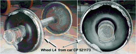
Car CP 521173, the 39th car, was the first car to derail. It came to rest upright approximately 2000 feet from the point of derailment (POD), still coupled to the head end of the train, and with only the lead truck derailed. Car CP 521173 was transporting four containers, two of which contained a regulated product, thioglycol (UN 2966, poison, Class 6). These containers were not damaged. No other dangerous goods were involved in the derailment.
Subsequent site examination determined that the L4 wheel on car CP 521173 was damaged. Approximately 60 per cent of the outer rim was missing.Footnote 11 The south wheels on the lead truck had dropped to the gauge side of the rail and the north wheels had dropped to the field side. Wheel marks on the ties and tie plates indicated that car CP 521173 had derailed east of the Garden Street overpass. The following two cars had uncoupled from the train. The trailing truck of the lead platform on car TTAX 653749, an articulated spine car, had derailed and came to rest just west of the Garden Street overpass. The remaining four platforms on car TTAX 653749 had derailed and lost their loads to the south side of the track. The last car, TTAX 78566, had also derailed and came to rest to the east and south of the overpass (see Figure 2).
After a small fire that had started during the derailment was extinguished, emergency personnel determined that the first platform from car TTAX 653749 had been dragged in the derailed position and fallen from the overpass onto an automobile. The two occupants in the vehicle were fatally injured. The small fire had started after the fuel tank from the automobile had ruptured and the fuel had ignited.
Approximately 200 feet of track at the derailment site was destroyed. Further site examination revealed that the south rail had fractured at Mile 178.20, approximately 300 feet east of the Garden Street overpass. Continuing east from that location, impact marks were observed on the gauge side of the head of the south rail.
1.3 Damage to track infrastructure
Table 1 provides a list of some of the rail damage that occurred after the passage of train 239. Within a distance of approximately 50 miles, between Colborne and Whitby, there were seven broken rails and nine other locations with rail fractures. These rail breaks and fractures all occurred on the south rail. There was also visible damage to the top of the rail in numerous areas, with many of these locations close to the rail breaks.
| Location of damage (mile) | Type of rail damage | Speed of train 239 when the 39th car was at this Location (mph) |
|---|---|---|
| 121.10 (ColborneFootnote *) | Broken rail at switch | 55 |
| 131.18 | Cracked bolt hole at switch | 30 |
| 154.94 | Broken stock rail into switch | 46 |
| 155.80 (LovekinFootnote *) | Broken rail | 46 |
| 163.72 | Split web | 33 |
| 165.50 | Split web | 45 |
| 165.56 | Split web | 48 |
| 165.67 | Broken rail | 49 |
| 166.92 | Cracked bolt hole | 56 |
| 167.98 | Split web | 58 |
| 168.38 | Transverse defect | 58 |
| 168.50 to 168.70 | Gouges on the gauge side of the rail head | 59 |
| 168.70 (DarlingtonFootnote *) | Broken rail | 59 |
| 178.20 (WhitbyFootnote **) | Broken rail | 51 |
1.4 Other damage
The Garden Street overpass was damaged during the derailment. The railing on the south side of the overpass was torn away. The bridge abutment sustained minor damage from falling rolling stock and containers. The road surface and light standards sustained minor damage. However, the structural integrity of the bridge was not compromised.
1.5 Personnel information
1.5.1 Train crew
Between Smiths Falls and Whitby, train 239 was operated by three different crews. Each train crew consisted of a locomotive engineer and a conductor. Crew 1 operated the train from Smiths Falls to Trenton; Crew 2 from Trenton to Port Hope; and Crew 3 from Port Hope to Mile 178.20. All three crews were qualified for their respective positions and met fitness and rest standards.
1.5.2 Rail traffic control
The events described in this report occurred during the work shift of three rail traffic controllers (RTC 1, RTC 2 and RTC 3) at CPR's Montréal rail traffic control office. The three RTC work shifts coincided with work shifts for two assistant managers, rail traffic control (AMRTC 1 and AMRTC 2). The RTCs and AMRTCs during these work shifts were qualified for their respective positions. The work shifts covered the following periods:
| Staff member | Shift start | Shift endFootnote 12 |
|---|---|---|
| RTC 1 | January 13 2230 | January 14 0630 |
| RTC 2 | January 14 0630 | January 14 1430 |
| RTC 3 | January 14 1430 | January 14 2230 |
| AMRTC 1 | January 14 0630 | January 14 1830 |
| AMRTC 2 | January 14 1830 | January 15 0630 |
RTC 3Footnote 13 had been working for CPR since 1997, initially in the S&C Department as a gang helper. He qualified as an RTC in April 1999. Since that date, he worked as an RTC in the Montréal office. The RTC passed a re-certification exam in April 2003. Since November 2003, he was assigned to the Belleville RTC desk.
AMRTC 2Footnote 14 had been working as an AMRTC since 2001. Before this date, he had worked as a relief operations manager in the Crew Management Centre for six months. He also spent two years before that as an RTC in the Montréal office.
At CPR, all AMRTCs have had prior experience as RTCs. AMRTCs receive six weeks of initial on-the-job training where they shadow management staff within the rail traffic control centre.
1.6 Particulars of the track
The Belleville Subdivision consists primarily of a single main track running in an east-west direction from Mile 0.0 at Smith Falls to Mile 211.5 at Toronto. There are numerous sidings on this subdivision to permit the passage of opposing movements. The maximum authorized speed is 60 mph. There were no speed restrictions in effect in the vicinity of the derailment.
On 14 January 2004, a number of cold weather restrictionsFootnote 15 were in place on portions of the Belleville Subdivision:
- GBO No. X318 - Between Mile 0.0 to signals 1960/1960B (at Mile 196.0), when a HBD transmits a temperature of -34°C or colder, do not exceed 35 mph.
- GBO No. T742 - Between signals 1960/1960B (at Mile 196.0) and signal 2094 (at Mile 209.4), when a HBD transmits a temperature of -34°C or colder, do not exceed 35 mph.
- GBO No. X377 - Between Mile 22.0 and Mile 58.0, Mile 73.0 and Mile 89.0, and Mile 158.0 and Mile 171.0, when a HBD transmits a temperature between -25°C and -34°C, do not exceed 35 mph.
In the area of the derailment, the track consisted of 136-pound continuous welded rail (CWR) in curves, and 132-pound CWR on tangent track. The 136-pound rail was manufactured in 1996 by Sidney Steel and was laid in 1997. Eccentric 14-inch double-shouldered tie plates, secured by 5 six-inch spikes, were used to fasten the rail. The ties were treated hardwood, with approximately 60 ties per 100 feet of track. The rail was anchored every tie. The ballast consisted of crushed granite rock.
Trains travelling westward through the derailment area negotiate an ascending grade of 0.8 per cent from Mile 177.1 to Mile 178.0, followed by a descending grade of 0.8 per cent from Mile 178.0 to Mile 178.4. Approaching Mile 178.0, westward trains travel from tangent track into a three-degree, left-hand curve, which has four inches of superelevation.
1.7 Track inspection and testing
To ensure safe train operation, CPR conducts inspection programs to help identify track irregularities and to plan track maintenance. These programs include track evaluation car (TEC) testing, rail defect testing, annual walking inspections, monthly inspections from motor vehicles, and semi-weekly visual inspections.
On the Belleville Subdivision, the track geometry was tested on 08 October 2003 using CPR's TEC. During this test, there were no exceptions noted in the vicinity of the derailment. The rails were tested by the rail flaw detector car on 03 December 2003. No anomalies were observed in the vicinity of the derailment.
The semi-weekly inspections were performed by the assistant track maintenance supervisor (ATMS) from a hi-rail vehicle. Before the occurrence, the last semi-weekly inspection was conducted on 12 January 2004. During this inspection, no significant defects were noted in the vicinity of the derailment.
1.8 Wayside inspection systems
CPR has equipped its rail network with electronic wayside inspection systems (WISs) to assess the condition of rolling stock equipment while en route. These scanners, spaced approximately 25 miles apart along main line track, normally include a HBD for identifying overheated bearings, a hot wheel detector and a dragging equipment detector. WISs are only located on tangent tracks. The systems are not designed to detect rims that are starting to shatter.
In addition, CPR has implemented wheel impact load detector (WILD) technology to help identify wheels that exceed impact thresholds. There are no WILD systems located on CPR subdivisions between Montréal and Toronto.
1.8.1 Hot bearing, hot wheel and dragging equipment detector systems
The scanner at Mile 82.1 of CPR's Belleville Subdivision is a SERVO System 9000 HBD. In addition to identifying overheated bearings, this system is capable of detecting hot wheels and dragging equipment. These scanners are typically equipped with track-side detection equipment, wayside equipment, and message output equipment. Inputs from heat sensors, wheel sensing transducers and dragging equipment sensors are captured and stored in system memory. The scanner is also configured to measure and transmit ambient air temperature. As the train passes the scanner, the crew receives a temperature update. If the temperature is below the predetermined value for the preset cold weather speed restriction, specified in the relevant GBO, the crew must slow the train.
When scanner alarms are activated, trains have to stop immediately for inspection, unless an inspection location has been designated. Then, specific instructions apply, as set out in Section 5 of CPR's March 2002 General Operating Instructions (GOIs). The scanner at Mile 82.1 was identified as a location with a designated inspection point. CPR's timetable was used to determine where the inspection should be performed. For a scanner alarm at Mile 82.1, the designated inspection point for westward trains is Mile 86.8, near Thurlow.
1.8.2 Wheel impact load detector systems
The development and installation of WILD technology was an industry initiative. This system helps identify wheels that exceed impact thresholds so they can be removed from service before they cause damage to the track or to the rolling stock.
WILDs are normally installed on tangent track and are normally adjacent to existing WIS sites. These installations consist of a network of strain gauges placed on the web of the rail. The strain gauges measure rail deformation under traffic. The system determines the impact load generated by each wheel and matches each measurement to a specific wheel position on the rail car.
CPR's WILD sites were selected primarily based on traffic patterns, interchange points and the availability of mechanical staff to respond. There are no WILD sites on the Winchester and Belleville subdivisions between Montréal and Toronto. However, rail traffic entering this corridor will pass through at least one WILD site; either on the Lacolle Subdivision (south-east of Montréal), on the MacTier Subdivision (north of Toronto), or on the Galt Subdivision (west of Toronto).
The car with the damaged wheel, CP 521173, last passed over a WILD detector on 07 January 2004 at Guelph Junction. At that time, no exceptions were noted.
1.9 Rail car inspection
Rail cars are inspected according to the Railway Freight Car Inspection and Safety Rules, as approved by the Minister of Transport. Where a certified inspector is on duty, safety inspections must be performed at designated inspection locations.Footnote 16 During a safety inspection, each component of a car is examined and checked using measuring devices and gauges, when required. Measuring devices are only applied to wheels when the inspector identifies a wheel that appears to be outside of standards. For wheels, only surface defects, such as shells or spalls, can be identified during these visual inspections. At designated locations where a certified car inspector is not on duty, an inspection will be conducted by the operating crew of the train.Footnote 17
In addition to inspections defined in the Railway Freight Car Inspection and Safety Rules, other pre-departure and en route train inspections are conducted as required (for example, brake tests, pull-by inspections).
1.9.1 Inspection of train 239 before Lonsdale
On 13 January 2004, a safety inspection of train 239 was performed by a certified car inspector at Saint-Luc Yard in Montréal. During this inspection, no exceptions were noted for car CP 521173.
1.9.2 Inspection of train 239 at Lonsdale Siding
After the malfunctioning SBU was replaced at the Lonsdale Siding, the prescribed brake tests were performed. The conductor also performed a pull-by inspection on the south side of the train. During this inspection, he identified three cars with potential defects.
1.9.3 Hot wheel inspection of train 239 at Belleville
After receiving an alarm from the scanner at Mile 82.1, the crew consulted the train consist to determine the approximate location of the problem. The crew indicated to RTC 1 that the alarm corresponded to the location where a partially applied hand brake had just been released following the inspection at Lonsdale. It was likely a hot wheel and corrective action had already been taken. The crew received permission from RTC 1 to continue to Belleville at a reduced speed not exceeding 35 mph.
Upon arrival in Belleville, the conductor performed a pull-by inspection of the train. In addition, the crew of a stationary train in the Belleville Siding also conducted a pull-by inspection of train 239. Following these inspections, it was determined that car CP 506187 should be set out at the nearest available point.
1.9.4 Inspection of train 239 at Trenton
Crew 2 took possession of train 239 at 1306 on 14 January 2004. The crew members inspected the train and completed the prescribed brake tests.
1.10 Method of train control
Train movements on CPR's Belleville Subdivision are governed by the Centralized Traffic Control System (CTC) of the Canadian Rail Operating Rules (CROR) and supervised by an RTC located in Montréal. RTCs coordinate the safe, efficient movement of trains and track equipment across the railway network, while organizing work programs and optimizing traffic priorities to minimize train delay.
In CTC territory, electrical signals are sent through the rails, forming a track circuit. The track circuit is used to activate wayside signal light aspects, otherwise known as block signals, to control the movement of the train. The status of these signals is communicated to the RTC display screen to indicate whether the signal indication is permissive. Each electrical circuit corresponds to a track block. RTCs use a computer screen to monitor the progress of trains, the state of block signals and track blocking.Footnote 18 Whenever a track block is occupied by rolling stock or equipment shunting the track, a track occupancy indicator is displayed on the RTC computer screen. The track occupancy indicator is automatically activated when there is a train or equipment occupying the main track, when there is a broken rail within the track block, when there is an open main-track switch, or in cases of signal failures. These track occupancies appear on the RTC computer display as red-coloured track segments. Track blocks created by the RTC are blue in colour.
1.11 Rail traffic control operations at Canadian Pacific Railway
CPR manages traffic on its rail network from three rail traffic control offices: Calgary, Alberta, Minneapolis, Minnesota, United States, and Montréal.
1.11.1 Rail traffic control offices
The Network Management Centre (NMC) in Calgary is CPR's main rail traffic control office. This office contains RTCs, AMRTCs, operations managers, and rail traffic control senior management. In addition, this office provides rail traffic control support functions, including a rail traffic control rules specialist, a training manager and a staff member for on-the-job training. Strategic planning for the rail traffic control function is primarily carried out in this office.
The Calgary office controls movements on CPR's rail network between Vancouver, British Columbia, and MacTier, Ontario. In this office, there are 143 RTCs who are assigned to various work shifts and assigned to one of 27 RTC desks.
The office in Minneapolis controls movements on CPR's rail network within the United States. Rail traffic control operations in this office are carried out under Federal Railroad Administration (FRA) regulations.
1.11.1.1 Montréal rail traffic control office
The Montréal rail traffic control office controls traffic on CPR's rail network between Saint-Jean, Quebec, MacTier, Ontario, and Windsor, Ontario. In this office, there are 40 RTCs assigned to various shifts and assigned to one of nine RTC desks. Each RTC desk controls traffic in a particular subdivision. RTCs are responsible for
- providing control functions to ensure the safe movement of trains and other on-track railway equipment;
- minimizing delays to railway traffic; and
- making business decisions based on priorities established by the NMC.
In the Montréal office, there are two AMRTCs, alternating on 12-hour shifts. During the night shift, the AMRTC can call upon additional outside support staff, but not for rules-related matters. AMRTCs are responsible for ensuring safe rail traffic control operations and for ensuring that RTCs execute the operating plans established by the NMC. As part of these responsibilities, AMRTCs must liaise with operations managers in the Calgary office.
The Montréal office consists of a large room, with the RTC desks positioned at the edge of the room (see Figure 3). The RTC desks face away from the central area that is reserved for the train crew assignment desks. Each RTC desk is located in an office used by a single RTC during each shift. Each office is enclosed by sound-reducing walls and topped with transparent barriers reaching the ceiling. Each office has a windowed door that can be shut.
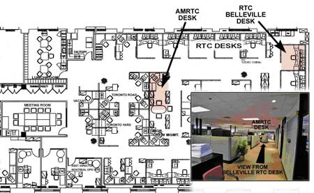
The AMRTC desk is located towards the back, facing away from the RTC desks. If an RTC calls the AMRTC, the call will go to voice mail if the AMRTC is not at his/her desk or if he/she is already on the phone.
1.11.1.2 Communication of safety issues between rail traffic control offices
Scheduled monthly conference calls involving rail traffic control managers from the three offices are conducted from the Calgary office. In preparation for these conference calls, reports summarizing safety statistics are prepared and distributed. These reports include information on rule violation trends and other statistics such as safety checks and reminders on rules.
Procedures that are common to all offices are summarized in core documents (for example, the RTC Manual). These documents are prepared, maintained and distributed from the Calgary office. However, within each rail traffic control office, these core documents are supplemented by regular bulletins. At the time of the occurrence, there was no formal procedure for sharing these bulletins between rail traffic control offices. As an example, the Calgary office had developed a checklist to assist the AMRTC when he/she was called for assistance. This checklist provides guidance to the AMRTC when discussing potential operational problems with an RTC. The AMRTC checklist procedure had not been communicated to the Montréal office, nor had a similar checklist been created for the Montréal office.
1.11.2 Management of the rail traffic controller's workload and mental fatigue
Individuals assess their workload according to the volume of work and their ability to do that work. To some extent, workload is linked to mental fatigue. A constantly high work volume or high work complexity will be progressively difficult to accomplish unless rest is obtained.Footnote 19
For rail traffic control operations, the amount of work demands placed on an RTC can be affected by many factors, including the following:
- the number of trains being managed;
- the mix of traffic (that is, passenger and freight trains);
- the need for train meets;
- opportunities available for train meets;
- the need to communicate with train crews and other field personnel;
- the ease of communications; and
- the number of disruptive or unusual events on the subdivision (such as track work or UTOs).
All RTCs must demonstrate the ability to meet the basic qualifications of the job. They must pass a qualification examination and must also demonstrate their ability to manage traffic on the particular subdivision where they are assigned. They are regularly assessed on their abilities and the quality of their work is frequently reviewed. Nevertheless, RTC skill levels do vary, along dimensions such as their ability to carry out traffic planning, their ability to perform under stress, their knowledge of the subdivisions and record-keeping skills. Because of the variance in skills, the perception of the workload will vary from one RTC to another under the same work demands.
The management of workload involves an assessment of both the work demands placed on individuals and their ability to meet those demands./p>
1.11.2.1 Rail Traffic Control Procedures Concerning Workload and Rest
Any railway position engaged in rail traffic control is classified as a safety-critical position,Footnote 20 as is any railway position directly involved in the operation of a train. As such, RTCs are subject to the rules concerning medical fitness for duty,Footnote 21 including assessment for medical conditions that could lead to impairment of cognitive function, including alertness, judgment, insight, memory and concentration.
RTCs typically work eight-hour shifts, plus 15 minutes before and after for the shift changeover. RTCs take breaks only when it is safe to do so, according to the projected traffic movements in their subdivision. This can lead to long periods without a break. If an RTC must leave a desk unattended, the RTC will normally ask a neighbour to monitor the emergency alarm. If the emergency alarm is activated while the RTC is away, the neighbour will then take the appropriate action until the RTC returns. When RTCs are able to take lunch breaks, they are allowed to be away from their desk for 20 minutes (paid time).
Each RTC desk is assigned a complexity rating, either Level 4 or Level 5. Under normal conditions, Level 5 desks are the most active and complex desks to manage. Given that the amount of traffic and type of traffic in a subdivision varies based on the time of day and day of the week, RTC job complexity ratings at CPR are assigned at the work shift and subdivision level. At the time of the occurrence, the RTC desk for the Belleville Subdivision was rated as Level 4. CPR uses a relief RTC to provide lunch relief for Level 5 desks and, time permitting, for Level 4 desks.
No practical training was given to the RTC or AMRTC on managing their workload or on understanding the consequences of failing to cope with their workload.Footnote 22 In addition, there are no written policies concerning the management of workload. Once RTC desks are rated, there is no further requirement to formally measure RTC workload. RTCs may however talk to their supervisor to indicate that they cannot cope with their workload. RTCs may also make a formal request for management to review and address a workload issue.
At CPR, a number of strategies are typically used to manage RTC workload, including the following:
- During operational planning meetings, AMRTCs provide input to the daily plans that will reduce the likelihood that RTCs are overwhelmed.
- If the workload is becoming unmanageable, the RTC may choose to slow or stop trains to reduce the pace of work.
- Relief rail traffic control staff may be asked to provide additional coverage to provide more opportunities for a rest break.
The AMRTC will typically monitor RTC workload during each work shift by
- assessing whether any planned operations or external conditions may overload the RTC;
- periodically displaying a copy of the RTC screen at his/her desk to view the level of traffic and events occurring in the subdivision; and
- periodically walking the floor and speaking with RTCs to assess workload levels, ask if assistance is required, and provide support when needed.
In the Calgary office, the following additional strategies are available to identify and manage workload issues:
- With a greater variety of desks, it is easier to make the initial assignment of RTCs to a desk that is appropriate for their skill level.
- Some CTC screens can be split between RTC desks, allowing work to be shared between two RTCs.
- Utility RTCs, who are not formally assigned to a particular desk, are available to help as required.
1.11.2.2 Rail traffic controller's workload on January 14
On the afternoon shift of 14 January 2004, the RTC workload for the Belleville Subdivision was very heavy, because
- a number of sidings were occupied by parked trains, increasing the complexity of forward planning to arrange the passage of opposing train movements on a single main track;
- there were a number of localized cold weather speed restrictionsFootnote 23 on the Belleville Subdivision, which made it more difficult to predict meet points;
- due to cold weather, the trains and track were encountering more problems than usual (for example, defective SBU, broken rail);
- train 239 had to be re-crewed twice as it had taken much longer than normal to travel through the Belleville Subdivision;
- a GBO involving cold weather slow orders had to be issued to all trains on and entering the Belleville Subdivision. To implement the GBO, the RTC was required to go through a detailed exchange of information with each train.
During the early part of the shift, the RTC left his desk twice for health breaks. As the afternoon shift progressed, the RTC workload became heavier. The RTC's interaction with other people in the subdivision became increasingly agitated and short, with the RTC expressing frustration at issues a number of times. In addition, the RTC sought advice from the AMRTC with increasing frequency as the shift progressed. During this period, the paperwork documenting significant events was not filled out completely.
AMRTC 2's shift started at 1800. At the start of the shift, there was the standard 30-minute handover with the departing AMRTC. Much of this time was devoted to discussing operational and financial issues related to the re-crewing of train 239. Since train 239's trip from Smiths Falls had been unexpectedly slow and had involved more crew changes than usual, the progress of train 239 across the Belleville Subdivision was a key issue for AMRTC 2. Once the handover was complete, AMRTC 2 began supervision of nine RTCs on 1000 miles of territory. The situation was dynamic and the AMRTC was required to balance competing demands, in what was assessed as a very heavy workload environment.
1.11.2.3 Managing workload and fatigue in air traffic control
Other transportation sectors have guidelines for the provision of breaks to reduce the effects of mental fatigue.
A working group studying the issue of mental fatigue in air traffic control (ATC)Footnote 24 identified the following best practices:
- Two hours on position followed by a meaningful break should be considered as the norm.
- Under high-volume conditions, breaks need to be more frequent.
- Where circumstances do not permit for the norm (such as in single-person tower operations), the period between breaks should not exceed four hours.
- Before exceeding four hours, the following alternatives should be considered: staffing, traffic restrictions, and temporary reductions in service.
- Emphasize the need for flexibility and apply "best fatigue management practices" to prevent the loss of vigilance and controller alertness due to acute fatigue.
It is recognized that ATC operations differ significantly from rail traffic control operations, and this is reflected in the specificity of these best practices. What is noteworthy, however, is that an industry effort was made to identify the effects of fatigue, its relationship to workload, and measures to mitigate the associated risks.
1.11.3 Documentation of safety-critical information
Train movements on a subdivision are typically documented using a rail traffic control planning sheet (originally called a "train sheet") and the Transfer Information Editor.Footnote 25 In addition, the RTC computer system records information such as GBOs, train clearances and track occupancy permits (TOPs).
While some of the information recorded by RTCs is for the purpose of business analysis, other information such as the occurrence of UTOs, communication failures, or impact of weather operations is more safety critical. For the purposes of this report, this information is described as safety-critical information. In some cases, defences are immediately put in place in response to this information; for instance, if a vehicle is foul of the tracks, a track block should be put in place. However, in other cases, such as bad weather or equipment failures, there is no immediate defence and it is the permanent record made by the RTC for himself/herself and the RTCs on subsequent shifts that serves as a reminder of the hazard.
In the past, rail traffic control planning sheets were the primary record of events in the subdivision and therefore strictly controlled. Railways now have the option of capturing the required information on a computer system, instead of on planning sheets. As a result, the majority of the rail traffic control events are recorded on the RTC computer system. Rail traffic control planning sheets, however, are still used to track and plan train movement. These documents are still a repository for information that is not recorded on the computer system.
From the rail traffic control training material,Footnote 26
. . . a Planning Sheet is laid out to provide the RTC with a visual reference of what is occurring on their territory. It is pre-formatted to:
- Allow RTC to organize train information in an effective manner,
- Assist RTC in ensuring all the required information is recorded,
- Assist RTC in recording information in a timely, consistent, legible, and accurate manner, and
- Assist others in readily locating information.
On most rail traffic control planning sheets, there is an area reserved for "Remarks/Notes." Any unusual conditions that may affect railway operations should be documented in that area. Unusual conditions include
- UTOs,
- track conditions that can affect safe movement,
- communication equipment failures,
- blocked sidings, and
- adverse weather.
Transportation Safety Board of Canada (TSB) investigators examined a number of train sheets. The examination revealed that there is considerable variation in the amount of information recorded by RTCs. For instance, a "Remarks/Notes" area was not allocated on the Belleville Subdivision planning sheet for the recording of safety-critical information. The RTC was expected to use the top right-hand corner of the sheet to record this information where space was available, or in the less prominent position of the back of the sheet.
The way that planning sheets should be used is covered in detail during initial RTC training. Occasional desk audits should identify deficiencies in RTCs' record-keeping practices.Footnote 27 However, according to the RTC New Hire Pre-Course Material, during times of high workload, RTCs may be allowed by a supervisor to cease recording necessary information on the planning sheet.Footnote 28 In practice, RTCs make decisions throughout a shift according to their workload about what information can be recorded on the planning sheet. While an RTC may be specifically brought in to help with documentation during periods of exceptionally high workload, this measure is rarely applied.
CPR's RTC Manual and CROR Rule 148 specify how an RTC should transfer information to the next RTC at shift change. Both documents clearly specify a list of information that must be transferred (that is, GBOs, Daily Operating Bulletins, TOPs, clearances and other operating authorities). The Transfer Information Editor computer program is used to record information from one RTC shift to be transferred to the relieving RTC. There is no specific requirement in the CROR for the RTC to ensure that unusual conditions in the territory are noted in the Transfer Information Editor, other than a general statement concerning "other necessary instructions and information" (CROR Rule 148 b (ii)). The CPR RTC Manual, section "Transferring Off Duty," page 28, states in part that the on-duty RTC being relieved must
3. Maintain all necessary instructions and information affecting train operations or track work required to be in writing in the Transfer Information Editor including . . . any instructions or information not protected by a computer assisted system pertaining to the safety and protection of trains, engines, track units and employees, including signal and/or switching blocking applied.
1.11.3.1 Rail traffic control planning sheet for January 14
On 14 January 2004, there were a number of unusual conditions related to train operations on the Belleville Subdivision. This information, including some safety-critical information, was not recorded, nor required to be, on the rail traffic control planning sheet, nor on the Transfer Information Editor.
- At 0016, there was an SBU valve failure on train 239.
- At 0259, there was a HBD hot wheel alarm at Mile 82.1 for train 239.
- At 0511, a decision was made to set off a car from train 239 at Belleville.
- At 1555, there was a UTO following train 239 at Mile 121.10 (Colborne).
- At 1645, the UTO at Colborne was identified as a broken rail.
- At 1905, there was a UTO following train 239 at Mile 155.80 (Lovekin).
- At 1931, there was a UTO following train 239 at Mile 168.70 (Darlington).
The investigation revealed that RTCs in the Montréal office did not have time to keep up with their paperwork in the days leading up to the occurrence.
1.12 Unidentified track occupancies
In CTC territory, when the track circuit is interrupted, the system "fails safe" and a track occupancy indicator appears on the CTC display. When train tags are used, the CTC computer screen will show the associated train tag when a track occupancy is due to an authorized train occupying the track block. However, if the track occupancy does not have an associated train tag, it is referred to as an unidentified track occupancy (UTO). A UTO is most commonly caused by a minor malfunction of the equipment that conducts the electrical signals (for example, wire break or transient error as the train crosses a switch point). In a small number of cases, a UTO can be caused by a rail break where there is complete separation of the two rail ends, interrupting the CTC signal circuit. If there are multiple broken rail locations within the same track block, the CTC screen will display only one UTO indicator for that block.
1.12.1 Rail Traffic Control Procedure for Unidentified Track Occupancies
With respect to UTOs, the RTC's responsibilities include:
- taking immediate action to identify any unknown occupancy, unusual indication within signaled systems, suspected track/signal defects or unusual condition under their control and reporting same to the proper authority for investigation.
- maintaining neat and concise records of delays to trains and for taking immediate action to report to proper authority and documents details, of all extraordinary occurrences, on prescribed forms in accordance with company instructions.Footnote 29
From CPR's RTC Manual, there is a single procedure documented for UTOs and for other signalling irregularities. This procedure requires that
- The RTC immediately advise the S&C centre of the event;
- Depending on the service area, the RTC may be required to first advise Engineering Services (ES);
- The RTC will route trains around the location wherever possible;
- Subject to other safety procedures, the RTC may operate trains through the affected area until the arrival of S&C or ES personnel.
In addition, the RTC Manual includes specific instructions for situations where there is more than one UTO following a train. However, these instructions are listed as an exception to the instructions for moving trains over a UTO rather than as a main point of the procedure.
The exception reads:
When more than one UTO appear on an RTC display/control panel after the passage of a train or engine, RTC must assume that the UTOs are likely rail defects.
In this circumstance, RTC must instruct the crew to stop and perform (or have performed) a pull-by inspection at a speed not exceeding 15 MPH, to check for defective equipment on their train or engine which could be causing UTOs.
In addition, RTC must not authorize any other train movements into the affected area until the cause of the UTOs is identified and it is determined that it is safe to do so.
Note: If UTOs appear behind a train or engine which has received a pull-by inspection as mentioned above, the movement must be stopped and a full inspection performed by qualified mechanical staff.Footnote 30
1.12.2 Rail traffic controller training for the unidentified track occupany procedure
In RTC training materialFootnote 31 implemented at the Calgary office, the UTO procedure is covered in an exercise that focuses on the recognition of a UTO behind a train movement and the implementation of the appropriate action. It is not known to what extent the UTO procedure was covered when the RTC in this occurrence was trained.
RTCs must be recertified within three years of completing their initial RTC training. An RTC Recertification Participants Guide (2002) is used to prepare for the recertification exam. In this guide, there are three questions on the handling of UTOs. During exam preparation, RTCs review this material as a group and provide verbal answers to the instructor.
1.12.3 Response to unidentifed track occupancies following train 239
On 14 January 2004, three UTOs occurred behind train 239 on the Belleville Subdivision.
1.12.3.1 Mile 121.10 (Colborne) - First unidentified track occupancy behind train 239
At 1555, the first UTO appeared behind train 239. In accordance with the UTO procedure, the RTC immediately called S&C personnel to ask them to investigate. The RTC also called the TMS and the Engineering Services (ES) track crew to provide them with advance notice. The RTC did not record the details of this UTO on the planning sheet, nor on other documentation.
At 1645, S&C personnel reported back that the UTO was caused by a broken rail. In addition, S&C personnel advised that they had to make some on-site adjustments to clear an activated level crossing signal. These adjustments resulted in the removal of the UTO indicator on the RTC display. The RTC then issued track protection to the track crew that was sent to repair the track. Upon issuing this protection, a blue indicator appeared on the CTC display screen.
Between 1647 and 1800, the RTC had numerous conversations with people in the field about the rail break and mentioned the broken rail to train 241.
1.12.3.2 Mile 155.80 (Lovekin) - Second unidentified track occupancy behind train 239
At 1905, approximately three hours after the UTO at Colborne, a UTO appeared at Mile 155.80, between the switches at Lovekin. At that time, the Cobourg Turn work train had just passed over the switch points at Lovekin and was travelling westward, with train 239 following closely behind. When this UTO first appeared, the signal display on the CTC screen turned yellow momentarily, indicating that there might be a signalling problem at that location. In addition, the situation was further complicated because the train tagFootnote 32 for the Cobourg Turn had earlier become disassociated from the train and had been incorrectly labelled "Cyborg." The RTC did not document this UTO on the planning sheet.
The RTC called train 239. Upon confirming that train 239 had passed the switch points, the RTC told the crew that there was a UTO on the main track at Lovekin. The RTC immediately called S&C personnel to advise of the UTO. The RTC then phoned AMRTC 2, but received his voice mail and did not leave a message. The AMRTC was not immediately available when called by the RTC because, between 1900 and 1915, the AMRTC was attending to two unrelated incidents, including a crossing accident that the Windsor RTC was handling and a derailment in Toronto Yard.
The RTC then called the TMS and told him about the new UTO left by a train and went on to describe how difficult it was to manage traffic on the subdivision as several sidings were now occupied.
- The Port Hope Siding was blocked with one car.
- The Darlington Siding was blocked with a train.
- The Spicer Siding had a car in it.
- The Colborne Siding was blocked by a train.
The TMS requested the RTC to issue a GBO to reduce train speeds on the Belleville Subdivision. The GBO indicated: "Do not exceed 35 MPH on main track between Mile 11.0 and Mile 173.0 Belleville Sub because of extreme cold conditions." The RTC did not issue the GBO to train 239 because it was almost out of the area covered by the speed restriction. Instead, the RTC determined that it was more important to issue the GBO to trains that still had a lot of track to cover in the area affected by the cold.
1.12.3.3 Mile 168.70 (Darlington) - Third unidentified track occupancy behind train 239
At 1931, less than 30 minutes after the UTO at Lovekin, another UTO appeared on the RTC screen just as train 239 passed Mile 168.70. At 1933, the RTC left a brief phone message with S&C personnel about another UTO and asked them to call him back. The RTC did not record this UTO on the planning sheet.
During this period, the RTC was continuing the task of issuing GBOs to trains on the Belleville Subdivision. The RTC also took a rest noticeFootnote 33 from a train and discussed an operational issue that had occurred in CPR's Toronto Yard.
At 1935, the RTC telephoned AMRTC 2 to seek guidance because he was concerned about the UTOs and that it may become very difficult to run trains across the subdivision. The RTC identified the UTOs and told the AMRTC that S&C personnel had been advised and that they were sending someone to look at the problem. After the AMRTC verified that train 239 was not in the area blocked by the UTOs, he advised the RTC to wait for the S&C personnel report and see what would happen.
From 1940 onwards, the RTC continued to issue GBOs and then left another message for S&C personnel about the UTOs. At this point, the RTC went to look for the AMRTC but could not find him. Soon after, the AMRTC walked over to the RTC office to discuss the UTO situation.
At 1941, the RTC called the TMS to notify him of the third UTO at Darlington. During this conversation, the RTC noted, for the first time, that the three UTOs had been left by the same train. The TMS advised the RTC to stop train 239.
At 1943, the crew from train 239 called the RTC to indicate that the train had gone into emergency braking on the main line at Whitby.
1.13 Regulatory Overview of Rail Traffic Control Operations
Transport Canada (TC) regularly audits rail traffic control operations against CROR requirements to identify non-compliance with operating procedures. In general, TC's audits focus on the quality and completeness of computer records rather than that of the paper records. Although generally not the focus of the audit, planning sheets may be reviewed to gain context on computer records.
On 31 March 2001, pursuant to Section 37 and Subsection 47.1(1) of the Railway Safety Act, the Railway Safety Management System Regulations came into force.Footnote 34 These regulations represent a fundamental change in the way that TC conducts regulatory overview. In particular, the Safety Management System (SMS) requires the railways to be directly responsible for the safety of their operations.
From TC document TP 13548, Railway Safety Management System Guide, the Railway Safety Act defines a Safety Management System to be
A formal framework for integrating safety into day-to-day railway operations and includes safety goals and performance targets, risk assessments, responsibilities and authorities, rules and procedures, and monitoring and evaluation processes.
A risk management process is defined as a process for
- identifying safety issues and concerns, including those associated with human factors, third parties and significant changes to railway operations, and
- evaluating and classifying risk by means of a risk assessment.
As part of the risk management process,
Railways are expected to do a thorough analysis of both new operations and significant changes to existing operations. . . . Where experience and a safety history are not available, formal analytical techniques should be applied. These techniques are more demanding in terms of data, time, effort and expertise; however, this extra effort is justified for new equipment, systems, operations, practices and procedures and should be considered a normal part of the process of implementing change.
Examples of significant changes requiring a risk assessment process include:
- railway company mergers,
- major organizational transitions,
- the introduction of new technology (e.g., Light Emitting Diodes), and
- major operational changes (such as new commuter lines and speed changes).
Under the Railway Safety Management System Regulations, railways are required to annually collect, analyse and maintain records of information relevant to their safe operation. The railways must submit a copy of this information to TC by March 31 of each year. TC will audit these submissions. The audits will "scrutinize the system and its documentation in detail to verify adequacy and effectiveness."Footnote 35
At the time of this occurrence, TC did not have a program in place to audit railway compliance to the SMS with respect to rail traffic control operations.
1.14 Main-track derailments during winter conditions
Based on TSB reported occurrences between 1999 and 2004, an analysis was conducted on all main-track derailments (MTDs) involving broken rails or broken wheels. During this five-year period, there were 123 MTDs. A graph of the number of MTDs (involving broken rail or broken wheels) by month is presented in Figure 4.
For MTDs involving broken rail, 64 per cent (that is, 51 of 80 derailments) occurred between December and March. The average temperature for these occurrences was -14.5°C, with the temperature ranging from -35.5°C to 6.0°C. For MTDs involving broken wheels, 86 per cent (that is, 37 of 43 derailments) occurred between December and March. The average temperature for these occurrences was -13.7°C, with the temperature ranging from -37.6°C to 8.6°C.
A review of Environment Canada weather data from 1971 to 2000 revealed that the temperature in the Belleville region typically reaches below -20°C four or five times per year. Temperatures below -30°C occur approximately once every three years.
Only once during the last 30 years has the temperature in this area dropped below -35°C.Footnote 36
1.15 Canadian Pacific Railway winter operating plan
CPR prepared a winter operating plan for 2003-2004. Each year, a winter operating plan was developed and built from the bottom up, with input from all field offices. This document, Winter Plan 2003/2004, was designed to assist employees during extreme winter operating conditions and to assist during conditions that cause "degradation in operating parameters."Footnote 37 The plan provided "an agreed upon level of customer service by implementing a proactive winter operating plan for each subdivision, yard and facility." The plan described the pre winter activities that are to be taken by field, engineering, and mechanical operations within each CPR service area. The winter plan did not include a detailed risk assessment of the impact the plan may have on CPR operations.
The plan introduced "predetermined procedures that will be executed when forecasted winter-related problems are identified."Footnote 38 These procedures were incorporated into a system of operational responses, referred to as Service Alert Levels (SALs). SALs were determined based on factors such as wind, ambient air temperature, snow forecasts, snow accumulation, number of broken rails, locomotive availability, and yard counts. Within the winter plan, personnel from the service areas were identified to implement and monitor the SAL system. SALs represent varying degrees of response, from Level 1 (mitigation - "emergent conditions"), to Level 2 (dynamic - "crisis conditions") to Level 3 (stabilization and recovery).Footnote 39
Once any or all thresholds were exceeded in a particular area, the implementation process was initiated. The NMC was notified, and through consultation with the respective service area(s), the need for the declaration of a SAL was confirmed, and if so, at what level.
According to CPR records, there was no SAL activated on the Belleville Subdivision on January 13 or January 14. The Belleville Subdivision went directly to SAL 3 on January 19, five days after the derailment, where it remained until it was removed on February 1.
1.15.1 Canadian Pacific Railway cold weather slow order policy
CPR implemented a cold weather slow order policy during winter operations in November 2003. This policy specified that
- Engineering Services would determine the cold zones (i.e., a risk of track failure exists when ambient air temperatures is below minus 25 degrees Celsius).
- The cold zones would be determined by analysing the number of prior defects, rail weight, speed and the presence of dangerous goods trains.
- The cold zones would be identified to train crews through GBOs.
- Ambient air temperature would be monitored at wayside HBD locations.
- Whenever the HBD alert broadcasts a temperature below minus 25 degrees Celsius, train speeds through that location would be reduced.
1.16 Transportation Safety Board of Canada Engineering Laboratory Examination
The number 4 wheel set from car CP 521173, consisting of the axle, the failed L4 wheel and the mate R4 wheel, were sent to the TSB Engineering Laboratory for analysis. In addition, two rails containing fractures, between Mile 121.10 and Mile 155.80, were sent to the TSB Engineering Laboratory. The laboratory analysis focused on determining the failure mode and cause. The results of the analysis are documented in TSB Engineering Laboratory report LP 016/2004.
1.16.1 Examination of Broken Rails
The fractured rail sections between Mile 121.10 and Mile 155.80 were analysed. The examination revealed the following:
- Both fractures were fresh overstress ruptures. The fractures occurred at thermite welds, with the fracture occurring in an upward direction from the base of the rail to the head of the rail (see Photo 1).
- The fracture at Mile 121.10 showed porosity at the field side base.
- The fracture at Mile 155.80 showed porosity and large slag inclusions at the centre of the base.
- No pre-cracks or signs of a progressive failure were observed in either rail fracture.

1.16.2 Examination of broken wheel
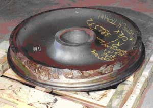
An examination of the wheel set (see Photo 2) verified that the wheels were class "C," cast, curved-plate Abex Southern Corporation (Southern) wheels that had been built to design CH 36. Design CH 36 is a "one-wear" wheel that is normally used on 100-ton capacity freight cars. The broken wheel (that is, L4 position) had been manufactured by ABC Rail (formerly Abex Southern Corporation) in Calera, Alabama, United States (code SO), in March 1988. The wheel had been mounted in June 1988 and the bearings had been reconditioned in October 1999. The wheel set was mounted to car CP 521173 in November 1999.
Detailed analysis of the wheels revealed the following:
- The L4 wheel fractured as a result of an overstress extension of sub-surface fatigue cracking and failed.
- Both the L4 and R4 wheels were within the specification for minimum tread thickness.
- No defects were noted in the bearings of the subject wheel set.
- Analysis of the mate wheel revealed a typical residual compressive stress of approximately 36 000 pounds per square inch (psi). With the amount of rim material missing from the failed wheel, it was not possible to conduct an analysis of its pre-fracture residual stress state.
- Porosity and hydrogen-assisted cracking were considered to be the root cause of the sub surface fatigue cracking in the failed wheel.
- Micro-structural inclusions visible at the macro level indicate that a significant amount of hydrogen gas was trapped in the wheel material during manufacture.
- Significantly less porosity and no sub-surface micro-cracks, nor conglomerations of ferrite, were observed in the mate wheel material.
- Both the failed and mate wheel material met the chemical and hardness requirements specified by the Association of American Railroads (AAR).
- A reduction in ambient temperature resulted in a decrease in fracture toughness for both the failed and mate wheel material.
Based on laboratory analysis, the wheel failed as a result of a manufacturing defect, originating in the wheel tread and propagating along the sub-surface boundary between the work-hardened surface and the tread interior to the rim. The manufacturing defect broke out as a shattered rim defect,Footnote 40 leading to the progressive wheel failure.
1.16.3 Ultrasonic Testing for Internal Wheel Defects
Although the failed wheel had been ultrasonically inspected at the time of manufacture, the manufacturing defect (that is, voids created by trapped hydrogen) was likely not large enough to be detected by the ultrasonic test equipment in use at that time. Only when micro-cracks initiated from the voids after continued service use would such internal defects have been detectable.
As of January 2003, wheels must be ultrasonically tested when they are re-profiled. Before 2003, there was no additional requirement to ultrasonically test wheels after their initial test at the time of manufacture.
1.17 Other Occurrences Involving Southern Wheels
The AAR requires member railways to document when wheels are removed from service as a result of a derailment or a line of road set-out. This information is captured on the AAR MD 115 form.
At CPR, between January 1998 and June 2004, there were 16 MD-115 reports of Southern wheels removed from service due to wheel defects, one of which was a straight-plate wheel. In 2 of these, a derailment had occurred. Of these 16 reports, 12 occurred during the winter months (December to March).
In comparison, at Canadian National (CN), between January 1999 and June 2004, there were 61 MD 115 reports involving the removal from service of a Southern wheel. In 9 of these, a derailment had occurred. It is not known how many of these occurrences involved a shattered rim defect.
Canadian railways do not know how many Southern wheels they have in service. Railways are not required to track the manufacturer and serial number of wheels applied to their fleets. However, it was indicated that neither CN nor CPR purchased Southern wheels. The Southern wheels that are now in their fleet were applied in the course of normal railway interchange operations under the terms of AAR interchange rules.
1.17.1 Main-Track Derailment due to Broken Wheel - Heron Bay
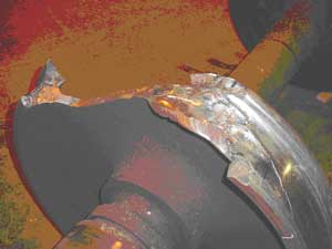
On 25 January 2002, CPR train 638-001, proceeding eastward at a speed of 37 mph, experienced a train-initiated emergency and derailed 30 potash cars at Mile 13.1 of CPR's Heron Bay Subdivision. At the time of the occurrence, the temperature was -20°C. Post-derailment examination determined that the train had derailed as a result of a broken Southern wheel (see Photo 3).
The broken wheel was a class "C," cast, curved-plate wheel, built to design CH 36, and had been manufactured by ABC Rail in Calera (code SO) in March 1996. The wheel was mounted new by ABC Rail in April 1996.
TSB Engineering Laboratory examination (report LP 007/2002) determined the following:
- The appearance of the fracture on the wheel (see Photo 3) was typical of a "shattered rim" as described in Rule 41 of the 2001 Field Manual of the AAR Interchange Rules.
- The wheel failed when a large progressive sub-surface crack reached a size such that a portion of the tread detached. The crack had been present for some time.
- The failed wheel had been the topmost wheel in the cooling pit, which has been identified as the most susceptible position for non-uniform cooling and entrapment of hydrogen.
- The ultrasonic inspection carried out immediately after manufacture would likely not detect isolated trapped gas or gas porosity. Hydrogen cracks would likely have not yet formed or were too few in number or size to be detectable by ultrasonic inspection.
- There was no indication that the failed wheel had been subjected to sustained heating damage from brake application or other cause.
1.17.2 Broken Wheel Occurrence - Telkwa
On 18 October 2004, while conducting a wayside inspection near Palling, British Columbia, a CN employee requested the crew members of westward CN freight train M-359-51-16 to stop and inspect their train. Upon inspection, it was determined that the 28th car from the head end, CNWX 111231, had a broken Southern wheel (see Photo 4). HBDs before the occurrence location were checked and no defects were noted.
The broken wheel was a class "C," cast, curved-plate wheel, built to design CH 36, and had been manufactured by ABC Rail in Calera in September 1995.
TSB Engineering Laboratory analysis (report LP 158/2004) determined the following:
- The appearance of the fracture on the wheel (see Photo 4) was typical of a "shattered rim" as described in Rule 41 of the 2001 Field Manual of the AAR Interchange Rules.
- The wheel failed when a large progressive sub-surface crack reached a size such that a portion of the tread detached. The crack had been present for some time.
- There was no indication that the failed wheel had been subjected to sustained heating damage from brake application or other cause.
1.18 Manufacturing of southern wheels
Although Southern wheels have not been manufactured since 2000, they represented as much as 10 per cent of the wheels in interchange service in North America at the time of the occurrence.
Southern manufactured its cast wheels using a top pour process. As part of this manufacturing process, a graphite mould on the rim was used to provide rapid solidification of the rim. The remainder of the wheel was placed in a sand mould. With this type of system, shrinkage porosity typically occurs in the thin part of the plate near the rim, rather than in the rim area. In comparison, other wheel manufacturers employ a vertical riser system.
After shakeout from the moulds and removal of the risers, the wheels are slow-cooled to remove dissolved hydrogen to acceptable levels and to control residual stresses. The slow cooling process takes place in a cooling pit, where up to 15 wheels are stacked one above the other. At this point in the process, the wheel hub is still hot (that is, approximately 2400°F), while the rim of the wheel may have cooled down to approximately 1200°F. The wheels will cool in the pit for approximately 12 hours. During this cooling period, heat in the wheel hub transfers out to the rim, re-heating the rim, and allowing trapped gas to escape through diffusion.
Using this cooling pit process, the top wheel and bottom wheels in the pit are more susceptible to cooling problems since these wheels only receive heat from one adjacent wheel. In addition, the topmost wheel is more susceptible to non-uniform cooling since heat escapes through the overlying insulated cover.
Recent research conducted by the wheel manufacturer suggests that some shattered rim failures may be associated with an ineffective cooling process, leading to excessive hydrogen in the rim. In this situation, hydrogen embrittlement can occur along the grain boundaries, leading to the initiation of sub-surface cracks.
2.0 Analysis
2.1 Introduction
In this occurrence, there were no train handling irregularities. In addition, the pre-departure and track-side equipment inspections did not identify any defects related to this accident. Post-derailment examination of the track and bridge structure in the derailment location did not reveal any pre-existing defects.
The analysis will focus on the sequence of events leading to the derailment of train 239. It will consider the role of the manufacturing defect in the L4 wheel on car CP 521173. Factors affecting RTC performance will be examined, including workload and its effect upon this particular safety defence.
2.2 The Accident
The 39th car in the consist, CP 521173, was the first to derail. The leading wheel of the leading truck (the L4 wheel) on this car was broken. The derailment sequence started when the train shifted to the high side of the curve as it entered the left-hand curve east of the Garden Street overpass at track speed. The damaged portion of the L4 wheel on car CP 521173 aligned with the head of the low rail, generating high impact loads on the rail.
The ambient air temperature on the day of the occurrence was as low as -30°C. The cold temperature induced thermal tensile stresses in the CWR, making the rail more susceptible to brittle failure. The high impact loads from the broken wheel, acting in combination with the thermal tensile stresses, initiated a brittle downward fracture through the base of the south rail, resulting in the derailment of the train.
The final position of the trailing truck on car CP 521173 and the lead truck of the following car, TTAX 653749, indicates that these cars likely remained on the track following the initial rail fracture. During the derailment sequence, subsequent wheels struck the broken rail head, creating additional rail fractures and enabling the last car, a five-platform articulated spine car (TTAX 78566, the 41st car), to derail to the inside of the curve. As this car diverged and dug in, it likely dragged the preceding five-platform articulated car (TTAX 653749, the 40th car) to the inside of the curve. At this time, car TTAX 653749 would have been at (or near) the Garden Street overpass. The derailment action likely caused this car to lean to the south and spill its car platforms and containers onto the roadway below, resulting in fatal injuries to the two occupants of the southbound vehicle.
Post-accident examination revealed that there was visible damage to the track structure on the south rail between the west switch at Colborne (Mile 121.10) and the POD. This damage was also consistent with tensile thermal stresses acting in combination with the high impact loads caused by the damaged wheel on train 239.
Laboratory analysis determined that the broken wheel resulted from a sub-surface crack, originating from a manufacturing defect. The defect propagated along the sub-surface boundary under the work-hardened surface of the wheel towards the rim until it broke out as a shattered rim defect. This likely occurred at or just prior to the west switch at Colborne. In left-hand curves, the fractured outer rim would move inward and align with the head of the rail, damaging the track and further damaging the wheel rim. The majority of the track damage occurred at locations where the train was travelling at track speed. The L4 wheel rim failed progressively over at least the last 57 miles of train 239's journey and over at least a five-hour period.
2.3 Broken wheel
Laboratory analysis determined that the L4 wheel on car CP 521173, a class "C" Southern wheel, failed as a result of a shattered rim defect. This defect originated from a sub-surface defect that had been in the wheel since its manufacture in 1988. The manufacturing defect was not detectable by ultrasonic test equipment in use at the Calera plant at the time. In addition, the wheel had not been re-profiled. If the wheel had been manufactured after January 2003, additional ultrasonic testing would have been performed on the wheel. Therefore, the defect in the wheel developed without detection, until its failure on 14 January 2004.
This occurrence was the second recent broken wheel derailment in Ontario involving a Southern wheel. On 25 January 2002, the failure of the R1 wheel (manufactured in 1996) on car CPLX 382532 resulted in the derailment of CPR train 638-001 at Mile 13.1 of the Heron Bay Subdivision.
Laboratory analysis of the defective wheels from the Whitby and Heron Bay derailments identified the following similarities:
- The wheels had not experienced an extreme overheating event.
- The wheels failed when a large progressive sub-surface crack reached a size such that a portion of the tread detached.
- Sub-surface fatigue cracking had been present in the wheels for some time.
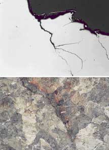
- The cracking had initiated at several locations in the wheel that contained material deficiencies, including porosity and inter-granular cracking (see photos 5 and 6).
Top: Unetched micrograph of sub-surface cracking coincident with the fracture origin area, X 25
Bottom: Etched micrograph showing inter-granular cracking, X 500
Top: Unetched micrograph of sub-surface cracking coincident with the fracture origin area, X 25
Bottom: Etched micrograph showing inter-granular cracking, X 500

Southern wheels have not been manufactured since 2000. At the time of the occurrence, they represented as many as 10 per cent of the wheels currently in interchange service in North America. It is likely that the majority of these Southern wheels did not undergo additional ultrasonic testing since manufacture because the requirement for testing during wheel re profiling came into effect in January 2003. A review of CPR and CN records between 1998 and 2004 identified 77 Southern wheel failures, resulting in 11 derailments in Canada. However, neither CN nor CPR purchased Southern wheels. The Southern wheels in their fleet were applied in the course of normal railway interchange operations under the terms of AAR interchange rules. In addition, since railways are not required to track the manufacturer and serial number of wheels applied to their fleets, the railways do not know how many Southern wheels they have in service. Without this information, railways are not able to determine the level of risk that Southern wheels present to their operations.
Even though evidence suggests that there may be a significant number of Southern wheels with manufacturing defects still in service, the magnitude of this problem is unknown. At the time of this occurrence, there were no formal industry efforts to assess the potential risk these wheels present in interchange service throughout North America. The absence of an industry program to assess and address the level of risk presented by Southern wheels currently in service increases the risk that Southern wheels with internal manufacturing defects will continue in service, leading to continued progressive broken wheel derailments.
2.4 Inspection and reporting of track damage
Track crews and S&C personnel are called out to inspect and, if necessary, to repair the track when a UTO occurs. At the time of this occurrence, on-site personnel was only required to report back to the RTC on the cause of the UTO. However, CPR procedures did not require S&C personnel or track maintenance crews to conduct a site examination to determine how the track was damaged, and to report those findings. Having this information in a timely manner may allow the railway to identify and remove faulty equipment from service before a derailment occurs.
2.5 Actions following the unidentified track occupancy at lovekin
2.5.1 Actions of the rail traffic controller
The progressive failure of the L4 wheel on car CP 521173 resulted in three separate UTOs on the Belleville RTC screen. Following each UTO, the RTC immediately notified S&C and ES personnel. However, the RTC did not instruct the crew of train 239 to stop and to perform a pull-by inspection following the second UTO,Footnote 41 nor the third UTO.
A number of factors may have affected the RTC's assessment of the situation:
- The RTC made a reasonable assumption that the cause of the UTOs was rail breaks. During extremely cold temperatures, rails are known to break more frequently. In contrast, a broken rail caused by a disintegrating wheel is a far more unusual condition.
- When the TMS requested the RTC to issue a GBO involving a slow order due to the extreme cold weather conditions, this action reinforced the RTC's assumption that the UTOs were related to the brittleness of the rail during cold conditions.
- When the second UTO occurred behind train 239, there was initial uncertainty over whether it was caused by the Cobourg Turn work train, by train 239, or by a signalling issue that temporarily appeared on the RTC screen. This initial uncertainty decreased the likelihood that the RTC would have immediately diagnosed the second UTO as a train 239 issue.
- The likelihood that the RTC would recall that train 239 was associated with the UTOs at Colborne and Lovekin was reduced because of
- the three-hour time period between the UTOs,
- the removal of the first UTO indicator from the CTC screen when it was replaced with a track block indicator, and
- the absence of a record about the first UTO on the rail traffic control planning sheet.
- In this occurrence, the UTOs were widely separated by distance (that is, non-consecutive track blocks). It is commonly assumed that, if UTOs are caused by damaged train equipment, the UTOs will occur in consecutive blocks.
- Within the RTC Manual, the location of the relevant procedure for a second UTO (as an exception to a different procedure) did not place sufficient emphasis on the requirement to stop the train for an inspection.
By the time the third UTO occurred, the RTC's workload had increased significantly. Several sidings were occupied and could not be used for train meets. There were a number of work blocks on the main line where damaged rail was being inspected or repaired. The RTC's request for help from AMRTC 2 was focused on the difficulty of managing trains under these conditions, rather than on the potential consequences of the UTOs. The RTC likely believed that the causes of the UTOs were understood and that the correct action (that is, notifying S&C personnel) had been followed. Only when the RTC started to explain the situation in detail did he recognize that both the second UTO and the third UTO had occurred behind train 239. As this was being recognized, the train derailed.
Heavy workload during the time when the UTOs occurred, in combination with the RTC's reliance on memory rather than documenting unusual conditions, contributed to the train not being stopped for inspection.
2.5.2 Actions of the assistant manager, rail traffic control
When AMRTC 2 received a call from the RTC concerning the number of broken rails occurring in his subdivision, he was occupied with several other urgent issues. Subsequently, the AMRTC listened to the RTC's concern that the subdivision might become difficult to manage because of the number of broken rails.
A number of factors may have affected the AMRTC's decision not to ask for further information or initiate immediate action:
- Under high workload, people make rapid decisions, often based on limited information, about which problems need to be addressed first.
- The RTC's description of the situation was that he had put in place the required actions following a broken rail. This description alone did not warrant immediate action.
- There was no formal mechanism to ensure that AMRTCs have the skills required to effectively manage several urgent tasks at once.
The fact that the AMRTC was the only manager present in the Montréal rail traffic control office during the night shift with significant rail traffic control experience and the lack of training in time management increase the risk that AMRTCs will not be able to effectively manage multiple urgent issues.
2.6 Management of the rail traffic controller's workload
The primary objective of rail traffic control is to ensure the safe and efficient movement of trains. For work functions that involve human monitoring of rail operations, it is important to ensure that the person's workload remains at a safe level so that this objective can be met.
At the time of the occurrence, there was evidence that the RTC was not coping well with the workload in the subdivision. He was not able to keep up with the required paperwork and was seeking help from his supervisor with increasing frequency. As his work shift continued, he was showing increasing signs of stress.
In addition, the RTC's workload was significantly increased by the process he was required to follow when issuing a blanket GBO. He was required to contact each train in the subdivision individually and go through a lengthy, detailed communication with each to ensure that the GBO had been correctly communicated. Although GBOs are issued as a defence against known hazards, the RTC must focus on managing the problem at hand. Consequently, the extra workload generated by the current communication method may reduce the RTC's effectiveness during an emergency situation.
In situations of high workload, deficiencies in the processes for managing the workload may lead to degradation of human performance and to errors. Although there were clear messages posted on office walls that address the importance of managing workload, there were gaps in CPR's policies, procedures and practices concerning the management of the RTC's workload as shown by the following examples:
- There were no policies concerning record keeping of any assessments of the RTC's workload. If workload is not recorded, it is difficult to effectively manage over time. However, if workload is recorded, rail traffic control management can study workload trends and review the effects of interventions.
- There was no training given to the RTC or AMRTC on managing their workload or on the consequences of failing to cope with their workload. Without this training, RTCs and AMRTCs will be less aware of the signs of not being able to cope with a heavy workload. In addition, they would likely not be aware of the strategies that they can put in place to reduce the problem.
- In the Montréal office, there were barriers to the AMRTCs with respect to monitoring how RTCs were coping with their workload. One of these barriers is as follows:
- The physical layout of the office, including cubicles with doors and the AMRTC desk facing away from the RTC cubicles, made it difficult for the AMRTC to observe workload issues. While this isolation was designed to remove distractions from the work environment, it also created a barrier to monitoring how well the RTCs were coping with their workload.
The lack of formal mechanisms for measuring the RTC's workload and the effects of workload on RTC staff increased the risk that excessive workload would occur, leading to reduced RTC performance that might affect the safety of railway operations.
2.7 Rail traffic control procedure for responding to unidentified track occupancies
The procedure for handling UTOs is described in CPR's RTC Manual. The UTO procedure specifies the required actions, potential causes and possible variations in local areas.
The effectiveness of the UTO procedure (with respect to equipment-related rail breaks) is reliant on the RTC's ability to recall previous UTOs. However, each UTO is displayed on the RTC screen as an isolated event. The CTC control systems are not normally designed to bring to the RTC's attention the occurrence of a second UTO behind a train. In addition, while there were general requirements concerning the need to document unusual conditions during the work shift, there were no specific requirements within rail traffic control procedures to document each UTO.
Within the UTO procedure, there were specific instructions to follow when a second UTO occurred behind a train. However, these instructions were located in the UTO procedure as an exception within the section that describes how to move trains over a UTO. By not placing these instructions in a more prominent area of the procedure, the importance of this instruction may be obscured, making it less likely that RTCs will immediately recognize the significance of a second UTO.
When a second UTO occurs, the instructions indicated that the RTC should "assume that the UTOs are likely rail defects." During periods of extreme cold when rail is more brittle, it is relatively common for rail breaks (that is, pull aparts) to occur, even under normal load. In this occurrence, in the time leading up to the accident, several rail breaks had already occurred on the Belleville Subdivision.
By indicating that the UTOs are due to rail defects, the UTO procedure emphasizes the potential severity of the UTO (that is, the UTO is likely to be more than just a fault in the signalling system). However, in doing this, the procedure reduces the likelihood that the RTC would recognize the more dangerous scenario involving rail breaks caused by defective equipment on a train.
In addition, a common assumption about UTOs is that, if the UTO is being caused by damaged equipment on the train, then the UTOs would occur in consecutive blocks. In this occurrence, the UTOs were widely separated by time and distance. Therefore, by not indicating that UTOs caused by defective equipment may be separated by large amounts of time or distance, the procedure does not direct the RTC to recognize this scenario.
Although the UTO procedure provided direction on what to do following a second UTO, the absence of information describing how rail breaks can occur, in conjunction with the order of information in the procedure, reduces the likelihood of RTCs taking appropriate action following a second UTO. This increases the risk that a train with defective equipment could continue in service, causing damage to the track infrastructure and leading to a derailment.
2.8 Documentation of safety-critical information
2.8.1 Procedures for train planning sheets
Historically, the planning sheet has played an important role as a job aid for RTCs when planning train movements and documenting safety-critical events. However, the increasing use of computer systems to automatically record rail traffic control activities has reduced the emphasis placed on written records. Although the use of planning sheets is covered in initial RTC training, CPR's RTC refresher training course does not include a section on the use of planning sheets, even though this is a critical RTC function that is infrequently audited.
Since rail traffic control computer systems do not record all necessary safety information, the reduced emphasis on written records increased the likelihood that safety-critical information (for example, potential unsafe conditions) may not be recorded and communicated to relieving RTCs.
2.8.2 Documentation during periods of high workload
During periods of high workload, CPR's RTCs were permitted to stop recording information on planning sheets, which may include safety-critical information. This is contrary to the purpose of recording the information (that is, to provide support for the RTC memory). Without recording this information immediately, there is an increased risk that safety-critical information may not be recalled when needed, nor communicated between RTCs.
2.9 Management of rail traffic controller mental fatigue
When workload is high and the tasks are complex, prolonged time on position can lead to mental fatigue and degraded performance. If suitable relief is available, CPR procedures allowed for lunch time relief for RTC staff on Level 5 desks, and resources permitting, on Level 4 desks. However, qualified relief staff was not always available, particularly in the case of the more complex Level 5 desks. In addition, RTCs normally scheduled their rest breaks within the opportunities afforded during the shift, as influenced by the rail traffic demand. In situations where RTCs are not able to take regular rest breaks, there is an increased possibility that fatigue may develop, leading to degraded performance.
In comparison, other industries have guidelines for the provision of rest breaks to reduce the effects of mental fatigue. In ATC, a number of strategies are used to reduce the likelihood of fatigue, such as limiting time on position to two hours and taking rest breaks more frequently when workload is high. When relief personnel is not available, alternative strategies such as traffic restrictions and reductions in service are considered.
CPR's approach to fatigue due to time on position does not take into account the variety of strategies that can be used to reduce the risk of fatigue leading to degraded RTC performance.
The lack of specific rules or guidelines concerning fatigue management and workload management for the safety-critical RTC occupation increases the risk that employees will not be sufficiently alert to control trains safely.
2.10 Safety communication between rail traffic control offices
In the course of normal operations, CPR's rail traffic control management staff communicated safety issues between offices. There were monthly conference calls where safety targets, rail traffic control issues and work activities were discussed. A number of centrally coordinated processes, such as the development of RTC training and the creation of RTC manuals, also generated consistency across the offices.
The core documents relating to rail traffic management were common to all CPR's rail traffic control offices. However, these documents were often supplemented by regular bulletins generated within the office. There were no formal procedures to share these bulletins with the other offices. In many cases, the sharing of bulletins was conducted informally. This approach to sharing may not be sufficient to ensure that all new risks and new safety strategies are shared. CPR's rail traffic control offices do not have an effective means to ensure that safety issues identified at one location are shared across the system, increasing the risk that identified hazards within rail traffic control operations may not be adequately addressed in all locations.
3.0 Findings
3.1 Findings as to causes and contributing factors
- As the train traversed the left-hand curve at 51 mph, the No. 4 wheel set from car CP 521173 shifted to the high side of the curve, aligning the damaged portion of the L4 rim to the low rail and generating a high impact load on the rail head.
- The cold ambient temperature induced thermal tensile stresses in the continuous welded rail, making the rail more susceptible to brittle failure. The train derailed when the low rail suffered a brittle downward fracture through its base as a result of the impact load acting in combination with the thermal tensile stresses.
- The wheel tread failed progressively over at least the last 57 miles (five hours) of train 239's journey. The initial fracture originated from a manufacturing defect. The defect had propagated along the sub-surface boundary under the work-hardened surface of the tread towards the rim, where it broke out as a shattered rim defect.
- As the wheel failed, it broke rail in several locations across the Belleville Subdivision, generating unidentified track occupancies (UTOs). Although three UTOs were displayed on the rail traffic controller's (RTC) screen and actions were taken to examine the locations, no action was taken to stop the train for inspection.
- The RTC's reliance on memory, rather than documenting unusual conditions, during a period of heavy workload contributed to the train not being stopped for inspection.
- Because the UTOs behind train 239 occurred at a wide separation of time (five hours) and distance, it was difficult for the RTC to recognize the relationship between train 239 and the UTOs.
3.2 Findings as to risk
- Eleven derailments in Canada between 1998 and 2004 have been linked to broken Southern wheels with manufacturing defects. The absence of an industry program to assess and address the level of risk presented by Southern wheels currently in service increases the risk that these wheels will continue to progress to in-service failure.
- At the time of the occurrence, Canadian Pacific Railway (CPR) procedures did not require dispatched Signals and Communications personnel and track maintenance crews to conduct a site examination to determine the likely cause of the damage and to report those findings. Without having this information, there is a risk that the railway will not identify and remove faulty equipment before a derailment occurs.
- During periods of high workload, CPR's RTCs are permitted to stop recording information on planning sheets. This increases risk that safety-critical information may not be recalled when needed, nor communicated between RTCs.
- The lack of formal mechanisms for measuring the RTC's workload and for training rail traffic control staff about the effects of heavy workload increases the risk that excessive workload will occur, leading to reduced RTC performance that affects the safety of railway operations.
- The lack of specific measures concerning workload and mental fatigue management for the safety-critical RTC occupation increases the risk that employees will not be sufficiently alert to control trains safely.
- CPR's rail traffic control offices do not have an effective means to ensure that safety issues identified at one location are shared across the system, increasing the risk that identified hazards within rail traffic control operations may not be adequately addressed in all locations.
- Although the UTO procedure provided direction on what to do following a second UTO, the absence of information describing how rail breaks can occur, in conjunction with the order of information in the procedure, reduces the likelihood of RTCs taking appropriate action following a second UTO.
4.0 Safety action
4.1 Action taken
4.1.1 Transport Canada's auditing and regulatory actions
On 23 January 2004, Transport Canada (TC) issued a Notice and Order to Canadian Pacific Railway (CPR) ordering that
Canadian Pacific Railway not operate railway equipment in the Province of Ontario, that has caused more than one unknown track occupancy in Centralized Traffic Control (CTC) territory after its passage, unless:
- the Rail Traffic Controller immediately notifies the crew to stop the railway equipment, and then notifies his or her supervisor;
- the railway equipment receives an inspection by qualified person(s). The inspection includes a pull-by inspection of one side of the equipment at a speed not exceeding ten (10) miles per hour, followed by a stationary inspection on the other side; and,
- the railway equipment with defective wheel(s) is removed from the consist:
- either at the existing location;
- or at the nearest location, travelling at a speed not exceeding ten (10) miles per hour, if it has been deemed safe by qualified person(s) to move.
TC conducted an audit of CPR's corrective action in September 2004, where the railway demonstrated improvements to its traffic control software, training and operational procedures to address deficiencies in the identification and response to multiple unidentified track occupancies (UTOs). Subsequently, the Notice and Order was revoked on 05 November 2004.
Further reviews and audits were conducted in December 2004 and January 2005 to evaluate the implementation of the new technology and procedures.
4.1.2 Inspection and reporting of damaged or broken rail
In February 2004, the TSB issued a Rail Safety Information Letter (RSI) concerning the inspection and reporting of damaged or broken rail. The RSI indicated that
CP procedures do not require S&C or track maintenance crews to also conduct a site examination to determine the likely cause of the damage, and to report those findings. Having this information in a timely manner may allow the railway to identify and remove faulty equipment from service before a derailment occurs.
In response to the RSI, CPR issued instructions to all Signals and Communications (S&C) and Engineering Services (ES) personnel that, upon determination that a UTO was a result of a rail break, personnel will check the track 300 feet in each direction to look for evidence of the cause of the rail break, and then report their findings immediately. CPR is also making this change to the applicable Standard Practice Circulars (SPCs).
4.1.3 Rail traffic control software enhancements
CPR enhanced its CTC software by implementing a feature to help distinguish a UTO (see Appendix A). Specifically, the CTC software was updated to display a warning message when a second UTO appears behind a train. This enhancement was implemented on 16 July 2004.
4.1.4 Unidentified track occupancy documentation and communicating procedures
CPR improved its UTO documentation procedures.
A specific area of the planning sheet has now been designated for recording UTO information (see Appendix B). UTO data must be recorded on the planning sheets for rail traffic controllers (RTCs) managing neighbouring subdivisions. In addition, the crew of the train behind which the UTO occurred must be advised. All RTCs received refresher training on the use of the planning sheet.
When a UTO behind a train appears on the RTC display, the assistant manager, rail traffic control (AMRTC) must be advised immediately. The information must then be recorded in the Transfer Information Editor by both the RTC and the RTC managing the neighbouring subdivision(s).
In CPR's General Operating Instructions (GOIs), the rail traffic control policy following a second UTO was revised. CPR's RTC Manual was also updated to reflect the changes (see Appendix C).
4.1.5 Inter-office safety communication
Formalized procedures were developed for sharing safety-critical information between rail traffic control offices. Rail traffic control management developed a common database where issues that may have broader operational relevance can be shared between rail traffic control offices.
4.1.6 Shattered Rim Failures in Southern Wheels
In June 2004, the Transportation Safety Board of Canada (TSB) issued a Rail Safety Advisory (RSA) concerning shattered rim defects in Southern (code SO) wheels. The RSA indicated that
… it is possible that the manufacturing deficiencies may be present in a wide population of Southern wheels. . . .
The presence of subsurface defects leading to in-service wheel failures can pose a significant risk to public safety. Because of the potential problems associated with code SO wheels, Transport Canada, in cooperation with the railway industry, may wish to examine a sample of code SO wheels with a view to analyzing their condition and assessing the magnitude of the risk of these wheels continuing in service.
On 09 July 2004, TC requested information from CPR and Canadian National (CN) on the issue of Southern wheels as raised in the RSA. The railways replied that this is a North American industry issue, and that the railways do not plan to take any unilateral action until the Association of American Railroads (AAR) has expressed industry opinions.
The AAR Wheels, Axles, Bearing and Lubrication Committee conducted a review of normalized failure and determined that Southern wheels manufactured in 1995 had a somewhat higher failure rate than Southern wheels manufactured other years. As a result, the AAR issued two circular letters.
- C-10097, effective 19 May 2005, implemented changes to AAR's Manual of Standards and Recommended Practices, Section G, Part II, Rule 1.4.7.4.8, prohibiting the return to service of one-wear, 100-ton CH-36 Southern wheels manufactured during 1995, once removed from a freight car.
- C-10104, effective 23 May 2005, implemented changes to Rule 41 of the Field Manual of the AAR Interchange Rules, condemning one-wear, 100-ton CH-36 Southern wheels manufactured during 1995, when on shop or repair track.
The effect is to see to the orderly removal of 1995 CH-36 Southern wheels from North American interchange service. In response to this directive and a CPR Test Department study of 30 randomly selected scrap Southern wheels, more broadly, the industry, through the AAR, has established a Wheel Consortium tasked with reviewing wheel failures and seeking means to reduce the problem.
CPR has taken the further step of prohibiting all of its wheel suppliers from re-using any Southern-marked wheels on wheel sets assembled and sold to CPR. Furthermore, in January 2006, the AAR implemented its second step in the planned removal of suspect Southern wheels from the North American interchange fleet.
4.2 Action required
4.2.1 Overview of rail traffic control operations
CPR, in response to this occurrence, has taken positive steps to improve systems and field inspection procedures designed to alert RTCs to track damage that may be caused by a specific train movement. These actions effectively reduce the risk that the origin of multiple UTOs will be misunderstood.
RTCs are responsible for moving rail traffic expeditiously and safely across the system. However, RTCs are also responsible for slowing or stopping train movements that may be affecting safe train operations, bearing in mind that train movements are not to be unnecessarily delayed. At times, particularly when operational conditions are deteriorating, these latter two responsibilities can be in conflict. When this occurs, RTCs are trained to seek the advice of their supervisor, the AMRTC.
However, conditions such as extreme weather can cause a general deterioration in operations and supervisors may be required to leave their station and make urgent events a priority. This makes supervisors less accessible, which increases the likelihood that, as in this occurrence, a developing unsafe condition will not be identified and rectified.
During the time leading up to the occurrence, both the RTC and his supervisor experienced a very high level of workload. The procedures and guidelines that were in place and designed to assist them in reaching the conclusion that train 239 was breaking rails did not provide them with clear, unambiguous clues. In this situation, and without a written record to aid memory, these experienced employees did not diagnose the problem in sufficient time to stop the train safely.
High levels of workload are not uncommon in the rail traffic control area. For example, inclement weather, broken rails, defective crossings, train derailments, and trespasser accidents may combine with regular, but high intensity, operational workload to increase the RTC's workload towards unmanageable levels. Although these circumstances are relatively common for rail traffic control operations, very high workload results in an increased risk of errors.
Some railway companies around the world train their rail traffic control staff to seek out the assistance of other experienced RTCs when direct supervisors are not immediately available. Staff and management are trained and experienced in recognizing signs of excessive workload and to seek assistance before operational conditions deteriorate to the point that safe train operation is compromised.
Canadian railways do not have similar protocols and training. When operational conditions are deteriorating, RTCs may neither be properly trained nor have access to the effective supervisory resources to enable them to balance competing responsibilities. The Board is of the opinion that, when failures occur in this environment, it is imperative that unsafe conditions be recognized and appropriate intervention be taken. Therefore, the Board recommends that:
The Department of Transport work with the Railway Association of Canada to implement rail traffic control protocols and training that will recognize periods of high workload and make safety paramount.
Transportation Safety Recommendation R06-01Footnote 42
Assessment/Reassessment rating: Satisfactory in Part
This report concludes the Transportation Safety Board's investigation into this occurrence. Consequently, the Board authorized the release of this report on 12 January 2006.
Appendices
Appendix A – Upgrades to Canadian Pacific Railway's centralized traffic control system for detection of unidentified track occupancies
(Document provided by Canadian Pacific Railway)
Effective Friday July 16th 2004 upgrades will be made to the CTC system. These upgrades will better assist the RTC in detecting Unidentified Track Occupancies (UTOs) left behind a tagged train.
UTO Detection
This upgrade will give RTCs an alert when possible UTOs are found. This upgrade is only capable of assisting RTCs, it is not an absolute tool for alerting RTCs to possible track defects. Daily in the territory controlled from GCS, there is over 1400 Unidentifed Occupancies shown on CTC panels. Due to the sheer volume of these occurrences, various filters have been put in place to avoid unnecessarily over alerting the RTC. For this reason, RTCs must be aware of the limitations of this upgrade and not rely solely on the alert.
When a track occupancy occurs behind a tagged train, the following alert will appear on the RTCs workstation:
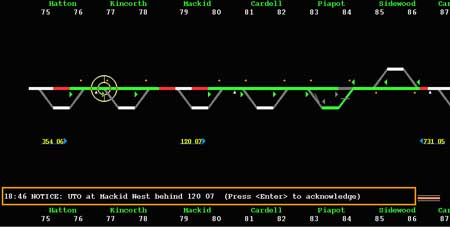
Response
Before acknowledging a UTO notice, the RTC must evaluate the situation to determine whether or not the alert is an actual UTO. If it is found to be a UTO, the RTC must follow the process for UTOs. The information must be recorded on the train sheet and the adjoining RTC and AMRTC must be notified.
Filters
The alert will only appear for occupancies which remain for a period greater than 1 minute. This use of this filter reduces the alerts to the RTC by 79% recognizing that:
- It is common to temporarily see a track light when a train moves over a controlled locations and splits. This is due to a lag in the signal system reaching the office and generally disappear in less than one minute.
The alert will only appear for occupancies left behind a tagged train. One of the filters in place is the requirement for the occupancy to be tagged. This filter is in place in recognition of the facts that:
- A number of these unidentified occupancies are related to regular operation and do not necessarily indicate a possible track defect.
- The RTCs do extremely well in terms of tagging train movements.
The alert will only appear on main tracks and signalled sidings. This filter reduces the alerts 1% recognizing the fact that:
- Movements departing yard tracks could appear to leave occupancies that can be related to open switches or other movements approaching the signal location.
- Any occupancy in a non bonded siding is related to the system and portrays no indication on possible defects.
The alert will only appear when the movement is not within the limits of any block. That block would include any blocking placed by the system in response to an authority; 564, 566, TOPBT, etc. or blocking placed manually; GBO blocking, manual block. Through filtering these type of occurrences the alerts are further reduced 1% recognizing that:
- A number of these unidentified occupancies are related to regular operation and do not necessarily indicate a possible track defect.
The alert will not appear for the following:
- Track occupancies that randomly appear, i.e. are not after the immediate passing of a tagged train.
- Track occupancies at crew change points between subdivisions where the following trains are typically not yet tagged.
- As stated above for:
- untagged train movements.
- occupancies that do not remain for longer than one minute.
- occupancies on yard approach tracks or non bonded sidings.
- in track blocked by an authority or manual block.
- occupancies that appear and are not following a tagged train movement, out of the blue.
This upgrade can be further changed based on input received from the RTCs. We recognize that the RTCs are busy performing other relevant functions and are concerned that unnecessarily alerting the RTCs may have a negative effect. If you are finding that you are receiving a large amount of unnecessary alerts, bring it to the attention of the Assistant Manager RTC.
Appendix B – Revised Canadian Pacific Railway rail traffic control train tlanning sheet
Appendix C – Changes to Canadian Pacific Railway's general operating instructions and RTC manual
SUBJECT: Additional instructions to GOI Section 1 - Page 10
POLICY FOR UNIDENTIFIED TRACK OCCUPANCY (UTO) BEHIND A TRAIN
These instructions are being put in place by Order of Transport Canada and to improve understanding and communication between RTCs and Train Crews.
POLICY FOR UNIDENTIFIED TRACK OCCUPANCY (UTO) BEHIND A TRAIN OR ENGINE
- When more than one unknown Track Occupancy Light appears on an RTC display screen after the passage of the same train or engine, the RTC must immediately notify the crew to stop and inspect.
- The speed of the movement must be immediately reduced to 10 MPH and a pull-by inspection performed at the first safe location, avoiding impediments to a safe inspection such as bridges.
- The inspection must include a pull-by inspection of one side of the equipment at a speed not exceeding 10 MPH, followed by a stationary inspection on the other side. BOTH sides of ALL cars and locomotives must be inspected for potential wheel defects. Inspection of entire train or engine movement must be completed even if defects are found.
Note: This inspection must be performed by either a crew member or qualified Field Operations personnel. - If any wheels are found or suspected to have defects, that piece of equipment must be set off at that location if possible, OR moved at a speed not exceeding 10 MPH to the nearest location where it can be set off, but only if deemed safe to move by the person making the inspection.
- Results of the inspection must be recorded on the Crew to Crew form, noting "UTO inspection".
- If another UTO is displayed behind a train or engine that has already received a UTO inspection, such movement must again be stopped immediately until full inspection can be made by a certified car inspector.
Note: All other provisions dealing with a UTO on page 5 of the RTC Manual remain unchanged.
RTC Record Keeping Between Adjoining RTC's:
In addition to the above instructions, immediately upon noticing that a train has left a UTO behind, the RTCs must:
- Record the train ID, subdivision and the location of the UTO below the train ID column on the top centre portion of the train-planning sheet.
- RTC's are responsible to verbally advise the adjoining RTC when a UTO is left on behind a train. (Train ID, subdivision and location) This information must be recorded on the train-planning sheet.
- This information must also be recorded in the Transfer Information Editor (TIE) by both RTCs until the train has left their subdivision.
Asst Director MOC
Appendix D – List of supporting reports
The following TSB Engineering Laboratory report was completed:
LP 016/2004 - Wheel Failure, Articulated Platform Car, Mile 178.2, Belleville Subdivision, 14 January 2004
This report is available upon request from the Transportation Safety Board of Canada.
Appendix E – Glossary
- AAR
- Association of American Railroads
- AMRTC
- assistant manager, rail traffic control
- ATC
- air traffic control
- ATMS
- assistant track maintenance supervisor
- cm
- centimetres
- CN
- Canadian National
- CPR
- Canadian Pacific Railway
- CROR
- Canadian Rail Operating Rules
- CTC
- Centralized Traffic Control System
- CWR
- continuous welded rail
- ES
- Engineering Services
- EST
- eastern standard time
- FRA
- Federal Railroad Administration
- GBO
- General Bulletin Order
- GOIs
- General Operating Instructions
- HBD
- hot box detector
- km/h
- kilometres per hour
- m
- metres
- mm
- millimetres
- mph
- miles per hour
- MTD
- main-track derailment
- NMC
- Network Management Centre
- POD
- point of derailment
- psi
- pounds per square inch
- RSA
- Rail Safety Advisory
- RSI
- Rail Safety Information Letter
- RTC
- rail traffic controller
- S&C
- Signals and Communication
- SAL
- Service Alert Level
- SBU
- sense and braking unit
- SMS
- Safety Management System
- Southern
- Abex Southern Corporation
- SPC
- Standard Practice Circular
- TC
- Transport Canada
- TEC
- track evaluation car
- TIE
- Transfer Information Editor
- TMS
- track maintenance supervisor
- TOP
- track occupancy permit
- TP
- Transport Publication
- TSB
- Transportation Safety Board of Canada
- UTO
- unidentified track occupancy
- WILD
- wheel impact load detector
- WIS
- wayside inspection system
- °C
- degrees Celsius
- °F
- degrees Fahrenheit