
Rail transportation safety investigation report R19T0147
Employee fatality
Canadian National Railway Company
Remote control locomotive system
Dual hump yard assignment YDHF60
Mile 0.0, Halton Subdivision
MacMillan Yard
Vaughan, Ontario
The Transportation Safety Board of Canada (TSB) investigated this occurrence for the purpose of advancing transportation safety. It is not the function of the Board to assign fault or determine civil or criminal liability. This report is not created for use in the context of legal, disciplinary or other proceedings. See Ownership and use of content.
-
Table of contents
Executive summary
On 15 August 2019, at about 0110Footnote 1 Eastern Daylight Time, the Canadian National Railway Company (CN) remote control locomotive system (RCLS) YDHF60 dual hump yard assignment (the assignment) was pulling 82 cars northward along track W100 in CN’s MacMillan Yard, which is located within the Concord industrial district of Vaughan, Ontario. The assignment was controlled remotely by a single CN yard operating employee (YOE) using a Beltpack. As the assignment negotiated a 15-degree left-hand curve (in the direction of travel), the trailing end of the 26th car and the 27th to 29th cars string-lined and derailed. The 29th car separated from the 30th car. The 30th car overturned and came to rest on the outside of the curve, parallel to the track. The 31st to the 34th cars derailed upright and coupled together. All 9 cars were empty multi-level vehicular flat cars (i.e., autorack cars). During the derailment, the 27th to 29th cars overturned on their sides to the inside of the curve and pinned the YOE under the 27th car. Consequently, the YOE was fatally injured.
The accident
On 15 August 2019 at about 0045, CN 2100 west industrial yard assignment coupled a cut of 34 loaded cars to the south end of 24 autorack cars that had previously been left standing on W100. The cut of 34 cars weighed 3391 tons and was 2074 feet long, and the 24 autorack cars weighed 1245 tons and were 2252 feet long. Five minutes later, the foreman of the CN 2100 assignment informed the trainmaster by radio that they had completed the switching and the trainmaster then notified CN Car Control.
At about 0100, the occurrence assignment arrived at W100 with a cut of 24 cars from track E008 that weighed 1938 tons and was 1652 feet long, and coupled the cut of cars onto the 58 cars standing on W100. With the locomotive hump set and the total of 82 cars joined together, the assignment weighed a total of 7086 tons and was 6166 feet long.
At the time, unbeknownst to the yardmaster, the yardmaster trainee, and the YOE, the cut of 34 loaded cars that had been recently added to the south end of the autorack cars placed 44% of the assignment’s weight in the rear 25% of its length, making it “tail-end heavy.”
After making the joint between the 24th and 25th cars, the YOE walked southward and released the hand brakes on the 3 autorack cars (25th car to the 27th car), then entrained the leading end of the 27th car while the assignment was stopped.
At about 0108, the assignment began to pull the 82 cars northward through the 15-degree left-hand curve en route to the west pullback track. About 2 minutes later, there was a communication failure between the controlling locomotive and the Beltpack. Following the loss of communication and as designed, the RCLS automatically placed the locomotives in idle, made a full service air brake application, applied the locomotive independent brakes and brought the assignment to a controlled stop.
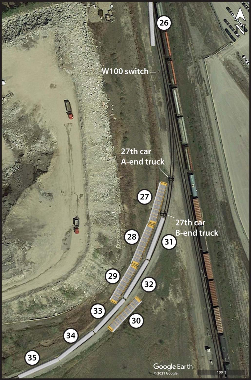
The investigation determined that the trailing end of the 26th car string-lined; the left side wheels of the trailing truck climbed the rail, derailing the car to the inside of the 15-degree curve. The 27th, 28th, and 29th empty autorack cars, which remained coupled together, rolled off their trucks, separated from the head-end cars, and overturned on their side about 2 feet from the track. The site observations were all consistent with string-line derailment characteristics. The YOE, who was riding on the left side of the 27th car, was pinned beneath the leading A-end and fatally injured.
The YOE’s actions while switching before the accident, and during RCLS operation using the Beltpack, were in accordance with company requirements and his training.
Operation of remote control locomotive systems
An RCLS operating system is programmed in such a way that the selected operating speed is attained as quickly as possible while operating within the parameters that are programmed into the RCLS to determine throttle output. Once the selected speed is attained, the RCLS automatically controls the locomotive throttle and brakes to maintain the speed.
While the RCLS’s aggressive throttle modulation is dependent on the differential between the current speed of the consist and the selected speed, it can also occur if the operator makes a series of small progressive speed increases or immediately selects Max speed (15 mph). As a result, at the time of the occurrence, RCLS operators, like the occurrence YOE, did not have the ability to directly control incremental locomotive throttle changes to facilitate the slow, smooth acceleration of an assignment.
Ratio of lateral-to-vertical forces and potential for derailment
A combination of lateral (L) and vertical (V) forces exists at the wheel-rail interface. The ratio of lateral-to-vertical (L/V) forces indicates the potential for a derailment to occur. When a high lateral force and low vertical force are present (e.g., as with an empty car), the high lateral force will tend to push the wheel flange up and over the gauge face of the rail, resulting in a wheel-climb derailment.
A single-wheel L/V ratio in excess of about 0.82 is indicative of the potential for a freight car wheel to climb (or lift) onto the head of a rail and cause a derailment. Empty long cars equipped with hydraulic long-travel end-of-car cushioning devices (EOCCDs), such as the autorack cars in this occurrence, are particularly vulnerable to these forces. A truckside L/V ratio in excess of 0.65 is indicative of the potential for a freight car truck to roll a rail and cause a derailment.
When a train is pulled through a curve, draft (tension) forces tend to stretch or “string-line” the train as wheel flanges are pulled taut against the inside rail of the curve. If the draft force generated by the locomotives is excessive or if there is a significant run-out of train slack, the L/V ratio can reach a critical level that results in a car wheel climbing, or lifting, onto the head of a rail and subsequently derailing.
Train dynamic simulations
Dynamic simulations are theoretical and are often performed in support of derailment investigations. One of the goals for any dynamic simulation is to identify the combination of the factors and forces that produce results which most closely match the physical evidence observed on an accident site. In this case, 7 different simulations were conducted.
Simulation 1 modelled the actual track surveyed and the actual consist with no brakes applied (rolling freely) while the train handling script used the actual train handling recorded on the LER. This confirmed that the tonnage added to the tail-end of the autorack cars on W100 left the assignment “tail-end heavy” with the lighter empty autorack cars located in a vulnerable position, and caused both single-wheel and truckside L/V ratios to exceed critical thresholds for the 26th to 28th cars.
Simulations 2 and 3, with brake retarding force on the 63rd car, produced similarly high L/V ratios on the 26th to 29th cars. The dynamic forces involved, with or without brakes applied on the 63rd car, predicted a significant potential for derailment.
Simulations 4 to 7 evaluated other mitigating strategies that could reduce the risk of a string-line derailment occurring.
Train dynamic simulations confirmed that the combined effects of aggressive throttle response due to RCLS programming, the vulnerable placement of empty autorack cars equipped with hydraulic EOCCDs between 2 heavier cuts of cars, and the weight of the trailing cut of 34 cars added to the assignment behind the autorack cars created the circumstances for this accident to occur.
Ensuring safety-critical procedures are carried forward
After a similar string-line accident that occurred on W100 in 2013, CN investigated the accident and implemented corrective actions. Although a procedure was implemented to prevent string-line accidents from occurring on track W100, it was not effectively documented or carried forward, and its use was discontinued, which eliminated a safety defense and likely contributed to this accident.
Safety action taken
Transport Canada
Transport Canada (TC) conducted an investigation under the Canada Labour Code, Part II (CLC II), and issued 2 directions to CN. TC reviewed CN’s corrective measures and deemed them to be satisfactory. The investigation results were shared with CN and its workplace health and safety committee as per CLC II requirements.
Canadian National Railway Company
CN issued Notices No. 1908-15 and 1908-21 that contained revised instructions for S-Yard industrial released cars, pulling cars on W100 track and train handling while pulling cars from W100 track.
CN training material was updated to highlight hazard areas for tracks with high curvature and instruct employees to ride either the locomotive or the trailing car on tracks with curves of over 12 degrees.
The 15-degree left-hand curve in track W100 was reconfigured to reduce the track’s curvature from 15 degrees to 12 degrees.
A process was developed to verify that safety-critical information communicated by a notice is also included in the next Summary Bulletin and, if required, the respective yard operating manual.
Working with General Electric and Beltpack manufacturer Cattron Intellectual Property Corporation, changes were made to RCLS programming to allow for a more gradual application of the locomotive throttle during RCLS operations.
1.0 Factual information
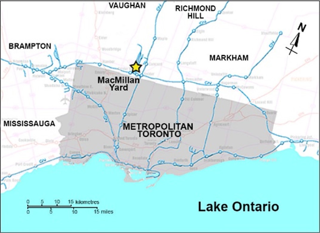
On 14 August 2019, at about 2330,Footnote 2 the Canadian National Railway Company (CN) remote control locomotive system (RCLS) YDHF60 dual hump yard assignment was switching cars at the north end of CN’s MacMillan Yard. The yard covers about 5 square miles in area and is located within the Concord industrial district of Vaughan, Ontario, just north of metropolitan Toronto, Ontario (Figure 1).
1.1 MacMillan Yard
MacMillan Yard is CN’s main rail classification yardFootnote 3 in Eastern Canada, where rail traffic is distributed by flat switching or humpingFootnote 4 rail cars into various tracks for placement on different trains. MacMillan Yard operations are conducted under Canadian Rail Operating Rules (CROR) Rule 105. Train movements are restricted to a maximum speed of 15 mph. They must also be able to stop within half the range of vision of equipment and stop short of a misaligned switch, a derail in the derailing position as well as blue flagFootnote 5 or red flagFootnote 6 track protection.
The yard processes up to 1 million cars annually. On any given day, there can be up to 150 operating employees working on 15 to 20 various local, yard, and hump switching assignments within the yard.
Arriving trains enter the yard from the York Subdivision or the Halton Subdivision at the south end of the lower yard. The trains are routed up the inbound tracks on the east side of the yard and set out in a receiving yard, located east of the main classification yard. Once the cars are set out in a receiving yard, the locomotives are removed, the rail cars receive a certified car inspection, the air brake system is discharged to empty and, if necessary, minor repairs are made. Yard assignments then flat-switch and hump the freight cars in order to redistribute them onto different trains for various destinations.
1.1.1 MacMillan Yard dual hump operation
Humping operations are carried out at the north end of the yard, where the crest of the dual hump is located. The dual hump yard has 2 pullbackFootnote 7 tracks (east and west) each of which is about 5600 feet long and is a designated point protection zone (PPZ).Footnote 8 As such, CN does not usually pull trains that are more than 5600 feet long from track W100 to the west pullback track. Various other tracks are used to access the pullback tracks.
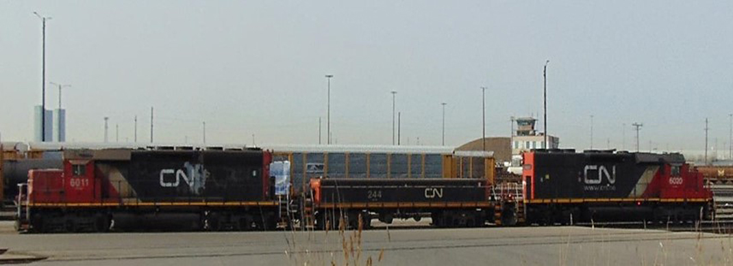
There are 2 dedicated hump set yard assignments. Each consists of two 3000 hp locomotives with a yard booster (slug) locomotiveFootnote 9 positioned between them (Figure 2).
The 2 hump set yard assignments operate independently of each other and operate 7 days per week, as they pull rail cars from yard tracks northward onto 1 of the 2 pullback tracks in preparation for humping.
Each assignment is controlled by a single qualified conductor, designated as a yard operating employee (YOE), operating an RCLS using a Beltpack.Footnote 10 Under normal operations, there is a continuous flow of cars being switched. When one YOE is humping cars, the other YOE is retrieving a cut of cars to switch on the other pullback track. When cars are switched onto a pullback track prior to humping, the speed selector of the Beltpack is usually set at 15 mph. Transponders along the pullback track right-of-way automatically begin to slow the northbound movement about 2600 feet from the end of track. From that location, additional transponders continue to reduce the locomotive’s speed so as to stop about 250 feet south of the end of the track. If the trailing car of the movement is on the pullback track before the locomotive is automatically stopped, the YOE will stop the movement.
Because these assignments only pull cars to the pullback tracks, then shove them over the hump, the YOEs working on these assignments rarely have a switch list as they are directed to pick up cars from various tracks. They do not necessarily know the length, weight or type of cars that the assignment is handling. While it is not unusual for the YOE to have to release 2 or 3 hand brakes securing cars that they are picking up on a track, the cars being picked up by a hump assignment do not usually have any air brakes applied.
A CN general supervisor of transportation (GST) and a yardmaster communicate with YOEs at frequent intervals as they prioritize car movements from various locations in the yard for humping.
A control tower is located at the crest of the dual hump. From the crest of the hump, freight cars from the pullback tracks are slowly pushed, uncoupled and released (Figure 3).
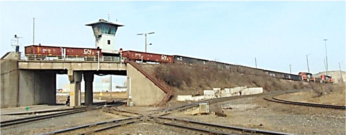
Each released car rolls freely southward down the hump, through a series of retarders that control the speed of the car and a variety of automatic switches that are used to direct the car into 1 of up to 80 classification tracks as trains are assembled.
Track W100 (W100) is about 2.7 miles long with a north-south orientation that extends along the western side of the yard. W100 is also a lead track that provides switching access to numerous nearby customers, which include an auto compound, multiple scrap steel and paper businesses, and warehouses.
When an assignment picks up cars from customers that have access to W100, the assignment operating crew visually inspects the cars, to ensure that no hand brakes or air brakes remain applied, before the cars are moved.
In general, at MacMillan Yard, a CN yardmaster oversees all movement of freight cars within the yard, while trainmasters are mostly in charge of assignments that move freight cars to and from customers. When cars are moved from a customer to MacMillan Yard, usually an operations coordinator, supervisor, or trainmaster notifies the CN Car Control Department. Car Control then updates the CN Service Reliability Strategy (SRS) computer database, which identifies in close to real time where cars are located on any track on the CN network in North America.
Usually, a CN yard assignment performs switching along W100 and then leaves the cars at the north end of W100 with an appropriate number of hand brakes applied to the northern-most cars in order to secure them. The cars from the auto compound are switched in the morning and those from the other industrial customers are switched at night, which means that cars are left on W100 twice daily.
At the time of the accident, there was no formal or informal process in place to prevent the heavily loaded industrial cars from being coupled behind a cut of empty multi-level vehicular flat cars (i.e., autorack cars) that were left standing at the north end of W100.
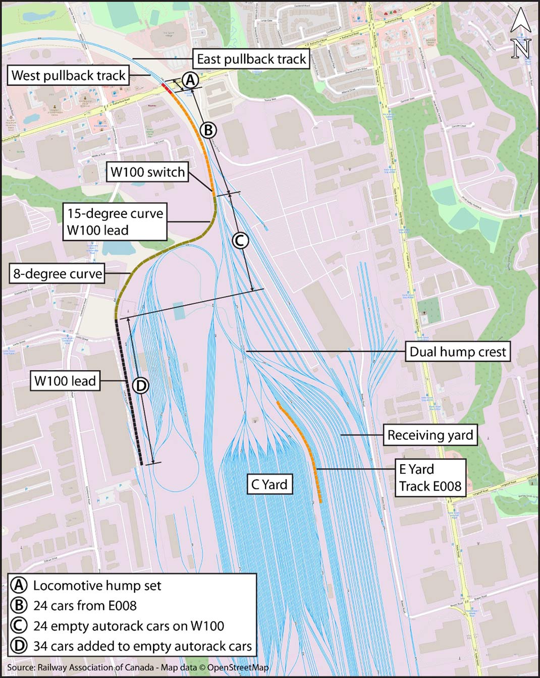
The north end of W100 joins the west pullback track at the W100 switch. The south end of W100 is tangent (i.e. straight) with a slight ascending grade. When proceeding northward approaching the north end of W100, there is an 8-degree right-hand curve followed by a short section of tangent track that transitions to a 15-degree left-hand curve that leads to the W100 switch and the west pullback track.
1.2 The accident
On 14 August 2019 at about 1000, a CN yard assignment pulled a cut of 24 long, empty autorack cars from the auto compound to the north end of W100. The autorack cars were each about 94 feet long and were equipped with 60-inch-long couplers and long-travel (10-inch) hydraulic end-of-car cushioning devices (EOCCD).
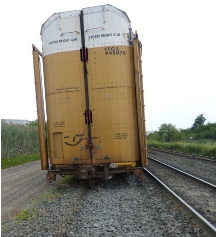
The autorack cars were left standing at the north end of W100 and secured with a hand brake applied to each of the 3 northern-most cars. These 3 autorack cars were located along the 8-degree right-hand curve, with their A-end leading (Figure 4). Since the 3 cars were oriented the same way, each of their hand brakes was located on the north side of the track, which corresponds to the outside of the right-hand curve and the inside of the left-hand curve.
At about 2330, the occurrence YOE arrived for work at the dual hump tower. CN supervisory staff on duty at the time included a GST, a trainmaster, a yardmaster and a yardmaster trainee. The YOE was familiar with yard operations, met fitness and rest standards, and was qualified for the position.
At about 2355, the YOE reported for duty to the yardmaster trainee. The yardmaster trainee assigned the YOE to the YDHF60 dual hump yard assignment (the assignment), which was operating on the east pullback track at the time.
The assignment was powered by a locomotive hump set consisting of locomotive CN 6020, yard booster CN 232 and locomotive CN 6019. The hump set was capable of producing up to 6000 hp; it weighed 512 tons and was 188 feet long. It was equipped with an RCLS and was operated by Beltpack. The YOE was instructed to finish shoving cars over the crest of the east hump track. The YOE completed the initial work assigned without incident and awaited further instruction.
On 15 August 2019, at about 0030, the yardmaster trainee instructed the YOE to pick up a cut of 24 cars that was standing in track E008 (E008). The cut of cars included 16 loaded cars and 8 empty cars, weighed 1938 tons and was 1652 feet long.
The YOE was also instructed to pull the 24 cars from E008 northward past the W100 switch, line the switch for W100, then reverse the assignment and couple on the cut of 24 empty autorack cars, which weighed 1245 tons and was 2252 feet long, that had previously been left standing on W100. Once coupled onto the cars that were standing on W100, the assignment was to pull all 48 cars on W100 to the end of the west pullback track in preparation for shoving them over the crest of the west hump track and humping them into the classification yard.
At about the same time, the CN 2100 west industrial yard assignment had picked up cars from nearby industries at the south end of the yard. At about 0045, CN 2100 west industrial yard assignment coupled an additional cut of 34 cars to the south end of the 24 autorack cars that already occupied W100. The cut of 34 cars comprised 26 loaded cars, 22 of which were open-top gondolas carrying scrap steel (the 59th to the 80th cars), and 8 empty cars. The cut of 34 cars weighed 3391 tons and was 2074 feet long.
At about 0050, the foreman of the CN 2100 west industrial yard assignment advised the trainmaster by radio that they had coupled 34 loaded cars to the south end of the cars that occupied W100. The trainmaster subsequently advised CN Car Control and the SRS system was updated.
At about 0055, the occurrence assignment coupled onto the 24 cars in E008 and pulled northward to the west pullback track.
At about 0100, the YOE stopped the assignment north of the W100 switch, detrained, and lined the W100 switch for track W100. The YOE then entrained the tail-end car and the assignment then shoved the 24 cars from E008 southward onto W100 and coupled onto the 58 cars that were already on that track. With all cars joined together, the assignment now comprised 2 locomotives and a yard booster (weighing 512 tons), and 82 freight cars (weighing 6574 tons) for a total combined weight of 7086 tons and length of 6166 feet (Appendix A).
After making the joint between the 24th Footnote 11 and 25th Footnote 12 cars, the YOE had to walk southward to release the hand brakes on the 25th, 26th and 27th autorack cars at the head end of the 58 cars that the assignment had just coupled onto. The YOE then likely entrained the leading end of the 27th car, TTGX 995540, while the assignment was stopped.
At about 0108, the assignment began to pull the entire 82 cars northward through a 15-degree left-hand curve en route to the west pullback track. After about 90 seconds, the Beltpack speed selector was placed in Coast, and 23 seconds later, while the assignment was travelling at about 10 mph, the selector was returned to 15 mph.
At 0110:29, a communication failure occurred between controlling locomotive CN 6020 and the Beltpack. Following the loss of communication:
- At 0110:31, the locomotives went to idle,
- At 0110:35, a full service air brake application was automatically initiated on the locomotive consist,
- At 0110:36, the locomotive independent brakes applied, and
- At 0110:57, the assignment came to a stop.
At about 0120, the yardmaster trainee realized that the switching in track W100 had not been completed and became concerned. The yardmaster trainee, the yardmaster and the GST each attempted to contact the YOE on the radio, with no response. Using yard video cameras to survey the area, the yardmaster trainee noticed that the assignment had come apart and the trainmaster was asked to go see what had occurred.
At about 0135, the trainmaster arrived at the W100 switch with a mechanical supervisor. They discovered that 9 empty autorack cars, located in the 26th to 34th positions behind the locomotives, had derailed. In particular, the 27th to 29th cars (3) had overturned on their sides to the inside of the 15-degree left-hand curve.
At about 0150, following a brief search, the YOE was located under the leading A-end of the overturned 27th car, TTGX 995540. Emergency responders were immediately dispatched, but unfortunately the YOE had sustained fatal injuries during the accident.
At the time of the accident, the ambient temperature was 17 °C, the sky was clear, and the wind was blowing at 21 km/h from the east.
1.3 Site examination
Railway personnel initially reported that a total of 9 empty autorack cars, located in the 26th to 34th positions, had derailed. The hand brakes on all these cars were released.
The locomotive hump set and the first 26 cars came to rest coupled together with the head end positioned about 2100 feet north of the W100 switch on the west pullback track.
The 26th car, empty autorack car TTGX 995076, had derailed but came to rest upright. The leading A-end truck did not derail but all 4 wheels of the trailing B-end truck were derailed in the ballast on the west side of the track, just north of the W100 switch (Figure 5). As the car came to rest, it struck and damaged the W100 switch. The remainder of the head-end cars were inspected with no defects noted.
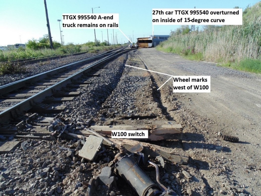
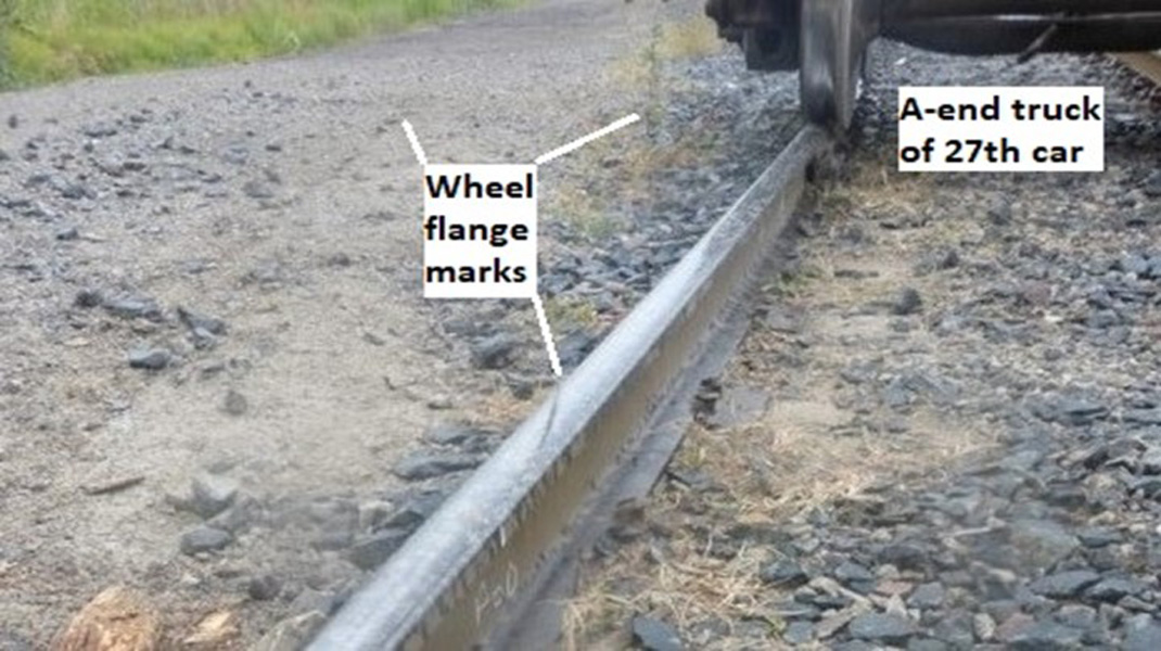
From the W100 switch, wheel marks were observed in the ballast extending southward for about 400 feet. The marks in the ballast stopped near the leading end of the 27th car, TTGX 995540. The leading A-end truck of TTGX 995540 remained intact, did not derail and rolled along the track clear of the car. It came to a stop on the rails about 40 feet north of the car (Figure 6).
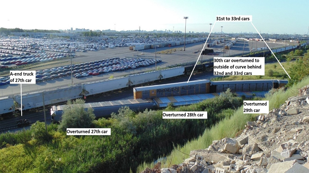
The 27th, 28th, and the 29th cars were coupled together, had all rolled off their trucks and overturned on their sides on the inside of the 15-degree curve (Figure 7).
Each of the 3 cars came to rest about 2 feet from the inside rail of the curve (Figure 8).
The trailing B-end truck of the 26th car had derailed.
The A-end truck of the overturned 27th car (TTGX 995540) rolled clear of the car and came to a stop on the track just north of the car. The B-end truck of the 27th car was generally intact but was impacted by the leading end of the 31st car (TTGX 982102) during the derailment. The B-end truck of the 27th car came to rest just ahead of the 31st car, which was adjacent to the B-end of the 27th car (Figure 9).
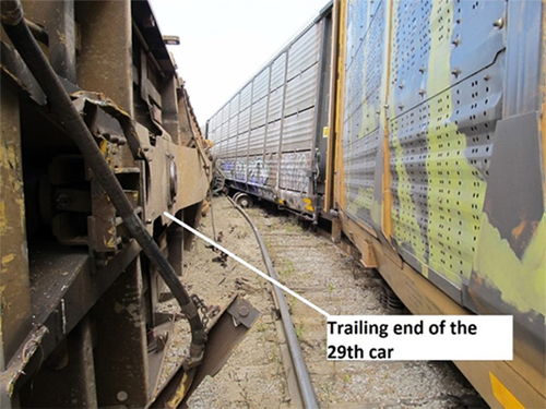

The trucks of the 28th and 29th cars were strewn about the site by the trailing cars as they derailed. The 29th car had separated from the 30th car. The 30th car had overturned and came to rest on the outside of the curve, parallel to the track.
The 31st to the 34th cars remained upright and coupled together. The outer rail of the curve had rolled to the outside (eastward) beneath these cars. The 31st to 33rd cars derailed all wheels along the track, while only the wheels on the leading end of the 34th car had derailed (Figure 10).
None of the trailing 48 cars (35th to 82nd cars) that remained on W100 had derailed. Subsequent CN examination of these cars revealed that the 63rd car, DJTX 318030, loaded with scrap steel, had its brake cylinder piston extended and its brake shoes pressed against the wheels. Although this indicated that the air brake may have been engaged on this car, no further follow-up was done at that time, and it was not confirmed on site whether a hand brake and/or air brakes were applied.
Short wheel flange marks were observed on the running surface of the west rail in the exit spiral of the 15-degree curve that transitioned to a tangent section of W100. The marks were located about 5 feet north of the overturned 27th car. The marks extended from the gauge side to the field side of the rail at which point they dropped off to the west into the adjacent ballast on the inside of the curve, and continued northward to the W100 switch (Figure 11).
The W100 switch and a total of about 350 feet of track were damaged.
1.4 Recorded information
The head-end locomotive CN 6020 RCLS was used to control the assignment. Although the locomotive event recorder (LER) data recovered from CN 6020 was corrupted, LER data from the trailing locomotive CN 6019 was successfully recovered. A summary of recorded information from the locomotive CN 6019 LER and the CN 6020 operator control unit (OCU) Beltpack log is contained in Appendix B. The times shown commence after the assignment made the joint between the 24th and 25th cars, at the head end of the 58 cars that the assignment coupled to on W100.
1.5 Canadian National Railway Company operating instructions
CN has various methods for issuing instructions to operating crews. These include General Operating Instructions (GOI) and system-wide bulletins issued by CN Operating Practices as well as local instructions in the form of yard operating manuals and notices. However, if local yard manuals and notices are not issued through CN Operating Practices, local safety-critical information may not be consistently updated or re-issued.
1.5.1 General Operating Instructions
CN GOI (2015) section 8 contains company guidance with regards to riding equipment. Item 12.4, Riding Equipment, states in part:
When riding equipment, employees MUST ALWAYS
[…]
- unless it is the trailing car in the movement, or the trailing end of the last locomotive in a consist, ride the side ladder on the leading end of equipment in the direction of travel;
[…]
1.5.2 System-wide bulletin
On 01 November 2018, CN Operating Practices issued a system-wide operating bulletin. Bulletin No. 015 2018 outlined that to reduce the risk of injury when entraining or detraining, effective 05 November 2018, the CN GOI were modified to prohibit entraining or detraining from moving equipment. Movements must be stopped prior to entraining or detraining at all times. This applied to all types of equipment.
1.5.3 MacMillan Yard Operating Manual
The MacMillan Yard Operating Manual contains securement instructions for different tracks at MacMillan Yard. Item 3.29 of the manual addresses hand brakes and requires hand brakes to be applied on track W100 as follows:
- 1 car = 1 hand brake
- 2 cars = 2 hand brakes
- 3 or more cars = 3 hand brakes
The expectation is that the hand brakes are always applied at the north end of the track due to the track grade.
1.6 Yard operating employee
The YOE began working at CN as a conductor trainee on 18 June 2018. He completed all required training and became a qualified conductor on 05 December 2018. During his training, the YOE had completed 7 shifts working the hump assignments at the MacMillan Yard dual hump.
Since qualifying as a conductor, between 05 December 2018 and 15 August 2019, he worked a total of 27 shifts as a YOE at the dual hump and was considered to be familiar with the tasks involved in humping operations.
The YOE was reported to have a good attitude, a strong work ethic, and seemed to enjoy the combination of analytical and physical challenges of the job. Despite having only 14 months of service, he was considered a capable employee who was knowledgeable about the work.
1.7 Canadian National Railway Company conductor and remote control locomotive system training
In Canada, newly hired CN operating employees must qualify as conductors and start out as conductor trainees. Trainees start with conductor training at the CN training campus in Winnipeg, Manitoba, where they receive 5 weeks of rules training, followed by 2 weeks of hands-on field training. Upon successful completion of the initial training, trainees return to their hiring terminal to complete their training.
Since all assignments at MacMillan Yard operate using RCLS, trainees receive 1 week of RCLS Beltpack training in conjunction with the regular conductor training program. Once the classroom and practical components are completed successfully, trainees put their knowledge into practice through supervised on-the-job training while working road and yard assignments.
To fully qualify as a conductor, trainees must also complete a minimum of 60 trips under the guidance of a qualified conductor. The on-the-job training trips are divided between freight service (main-track) and yard RCLS assignments. CN conductor training continues until the trainee is deemed to be a fully qualified conductor by a local manager. It usually takes between 5 and 7 months to become a fully qualified conductor. Once qualified, conductors can be assigned regular duties on either main-track or yard assignments.
1.7.1 MacMillan Yard remote control locomotive system training
The MacMillan Yard RCLS training consists of about 1 week of training that comprises both classroom training and field training. The classroom training requires trainees to review the Beltpack Operator Training Participant Manual with an on-the-job trainer (OJT).
During field training, OJTs provide trainees with MacMillan Yard familiarization training, which includes identifying areas of the yard where RCLS operation can be more challenging and tips for safely working in these areas.
1.7.2 Beltpack Operator Training Participant Manual
The manual covers the key components of a locomotive, how to initialize the RCLS, how to use the Beltpack, as well as some elements of train handling and troubleshooting. Module 7 of the manual discusses train handling and explains that buff, draft, vertical and lateral forces can affect how a cut of cars will handle when moving on a track. The manual outlines the forces involved and defines string-lining Footnote 13 as the tendency of a long cut of cars to shortcut a curve when being pulled (Figure 12), a problem that is amplified in a heavier train when handling light cars that are followed by significantly heavier cars.
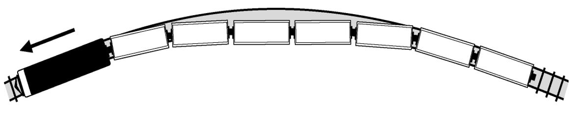
The manual also identifies that the risk of string-lining increases when handling light cars within a heavy train. However, the manual does not include more specific guidance for identifying conditions that are conducive to string-lining, nor does it contain tips for preventing a string-line event.
With regards to train handling, Module 7 of the manual contains the following instructions (in part):
Change speeds gradually — let the cars adjust to one speed before moving up or down to another.
[…]
When pulling from a Stop position, move the Speed selector to the Couple position (1 mph) for about 50 feet of movement. Once the cars are stretched, move the selector to your desired speed.
When stopping, move the Speed selector first to Coast for 5 or 10 seconds and then to Coast B position to allow the cars to bunch. Once you hear the slack gather, move the Speed selector to STOP for a quicker slack free stop.
A review of the Beltpack log revealed that the YOE’s use of the Beltpack was consistent with these instructions.
1.8 Operation of remote control locomotive system
RCLS is essentially a speed-based control system that automatically ramps up the throttle of the controlling locomotive in response to the RCLS operator selecting a speed. The RCLS consists of 3 main components:
- a remote-control locomotive(s) (RCL);
- an onboard control computer, mounted inside the RCL to interface with the controls; and
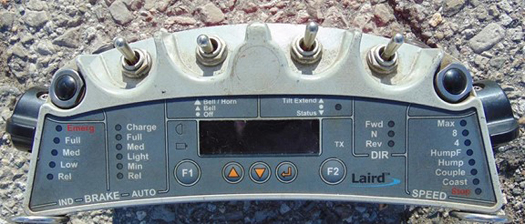
- an OCU, commonly referred to as a Beltpack. The OCU is a lightweight remote-control device that attaches to the operator’s safety vest.
Beltpacks are equipped with several safety features, which include:
- Tilt monitoring, providing “operator down” protection. Whenever an OCU is tilted more than 45 degrees, it transmits an emergency brake command that automatically applies the emergency brakes on the locomotive and any cars that are connected through the trainline.
- A loss of communication feature between Beltpack and controlling locomotive. When a loss of communication occurs between the Beltpack and the locomotive, the throttle is automatically transitioned from the selected throttle position to idle, and a full service air brake application is automatically initiated.
Beltpack operators choose from a range of pre-programmed speeds: Stop, Coast, Couple (1.5 mph), Hump (2.0 mph), HumpF (fast; 2.7 mph), 4 mph, 8 mph, and Max speed (15 mphFootnote 14). Once a speed is selected, the RCLS manipulates the locomotive throttle to attain the selected speed. Once the selected speed is attained, the RCLS automatically controls the locomotive throttle and brakes to maintain the selected speed within a range of ±0.5 mph. The system adapts to terrain characteristics reactively, without accounting for train length, tonnage, or slack.
When starting the movement from a stopped position, the rate at which the RCLS increases the throttle is determined by the difference between the selected target speed and the RCL actual speed. When the time interval between throttle changes is relatively large, it results in slower throttle increases. However, as the difference between the target speed and the actual speed increases, the interval between throttle changes decreases, which results in much quicker throttle increases.
The RCLS is programmed so that the selected speed is attained as quickly as possible while operating within the parameters that are programmed to determine throttle output. The speed configuration parameters that were programmed on the RCL at the time of the occurrence were the original speed controller parameters, as defined by CANAC Railway Services Inc.
When an operator increases speed on the OCU, the RCL consist is commanded to increase throttle. This can sometimes result in a rapid increase of the RCL throttle to the maximum notch 8 position. While this is dependent on the differential between the current speed of the consist and the selected speed, it can occur regardless of whether the operator makes a series of small progressive speed increases or immediately selects maximum speed, depending on the circumstances.
RCLS operators cannot directly control incremental locomotive throttle changes. This is a deliberate design attribute. The Beltpack RCLS was specified as a speed control RCLS. This requires that the RCLS be in complete control of the throttle activation.
In this occurrence, the YOE used a low speed setting to initiate the movement. Once all of the cars were moving, the OCU speed selector was moved to 15 mph as would be expected since the 15 mph speed selection is almost always used by all CN YOEs to complete the pullback operation when an assignment is operating within the hump pullback track PPZ.
Following the accident, a review of Beltpack downloads for other locomotives operating at the dual hump identified that the occurrence YOE’s operation of the assignment was consistent with assignments operated by other YOEs.
1.9 In-train forces
Couplers are installed on both ends of a freight car to allow cars to be assembled together in a train. Depending on the car’s design use, either standard draft gears Footnote 15 or EOCCDs are installed on both ends to help absorb the energy associated with train movements. Draft gears and EOCCDs are essentially shock absorbers designed to compress and extend by a certain amount when a force is applied to them. Due to this, the connection point between coupled cars will have some amount of slack (travel) depending on the draft gear characteristics.
The terms “slack” and “train slack” refer to the longitudinal movement or displacement at the ends of a car and the accumulative movement of cars within the train. The movement occurs as the draft gears are compressed in buff or extended in draft as in-train forces are transmitted between cars during operation. Train slack can cause speed differentials within a train in the form of a run-in Footnote 16 or run-out Footnote 17 of slack.
As a train starts moving forward one car at a time, the slack is pulled out. The amount of slack can vary depending on the type of draft gear or EOCCD installed on each car. For example:
- In a static position, about 1 inch of free slack exists at each end of a car. When 2 cars are connected together, about 2 inches of slack will exist at each car-to-car coupling.
- About 3.25 inches of additional movement, due to compression (buff force) or tension (draft force), can occur at each end of a car equipped with a standard draft gear.
- For a car equipped with EOCCDs, between 1 to 22 inches of additional slack is available at each end of the car, depending on EOCCD characteristics. The most commonly used EOCCDs have a pre-load requirement and between 10 inches and 15 inches of travel when compressed in buff. EOCCDs are also referred to as hydraulic cushioning units.
The empty autorack cars in this occurrence were equipped with an EOCCD at each end, with each EOCCD providing up to 10 inches of travel when fully compressed in buff. Each EOCCD had a 50 000-pound pre-load requirement, which means that a buff force of 50 000 pounds is required before the device begins to compress. When these EOCCDs are in the neutral position, there is only 1 inch of free slack at each coupler end. Consequently, despite these autorack cars being equipped with EOCCDs, free slack is taken up very quickly when transitioning from stop to full draft as they are pulled in a train.
EOCCDs are designed to dampen in-train forces and minimize damage to lading. However, the presence of a high number of EOCCDs grouped together on a train can also significantly increase the train’s total slack. When there are cuts of cars equipped with EOCCDs on a train, a locomotive engineer or an assignment operator must be vigilant in order to control the slack action. If care is not taken, a sudden run-out or run-in of the train’s slack can result in a train pull-apart, string-line or jackknife derailment.
The Association of American Railroads (AAR) Train Make-Up ManualFootnote 18 indicates that cars equipped with EOCCDs will add to train slack and can greatly increase in-train forces. In general, cuts of empty cars equipped with EOCCDs should not be placed ahead of large cuts of loaded cars equipped with standard draft gears for trains operating on main track. While this manual does not apply to yards, the in-train forces generated by such configurations may apply to certain situations in yards, depending on train and track configurations.
1.10 Canadian National Railway Company train marshalling rules
Approximately 10 years ago, CN developed a series of train marshalling business rules, primarily related to train weight distribution, in an effort to manage more effectively in-train forces for mainline operations. CN relies on its generalized train weight distribution rule (Rule 1) which is designed to prevent a train from having excessive weight on the tail end, a condition generally referred to as a “tail-end heavy” train. CN’s train marshalling Rule 1 requires that no more than 33% of the train weight should be placed in the rear 25% of the train’s length.
For CN mainline operations, CN train marshalling criteria do not specifically require the placement of empty and/or lighter loaded cars, such as autorack cars equipped with EOCCDs, at the tail end of a train.
CN train marshalling rules do not apply to any assignments that operate within a yard.
1.11 Assignment length and tonnage profile
The assignment length profile (Figure 14) displays the positions of the locomotive hump set, the 9 long empty autorack cars that derailed and the car in the 63rd position that was observed to have its air brake cylinder piston extended.
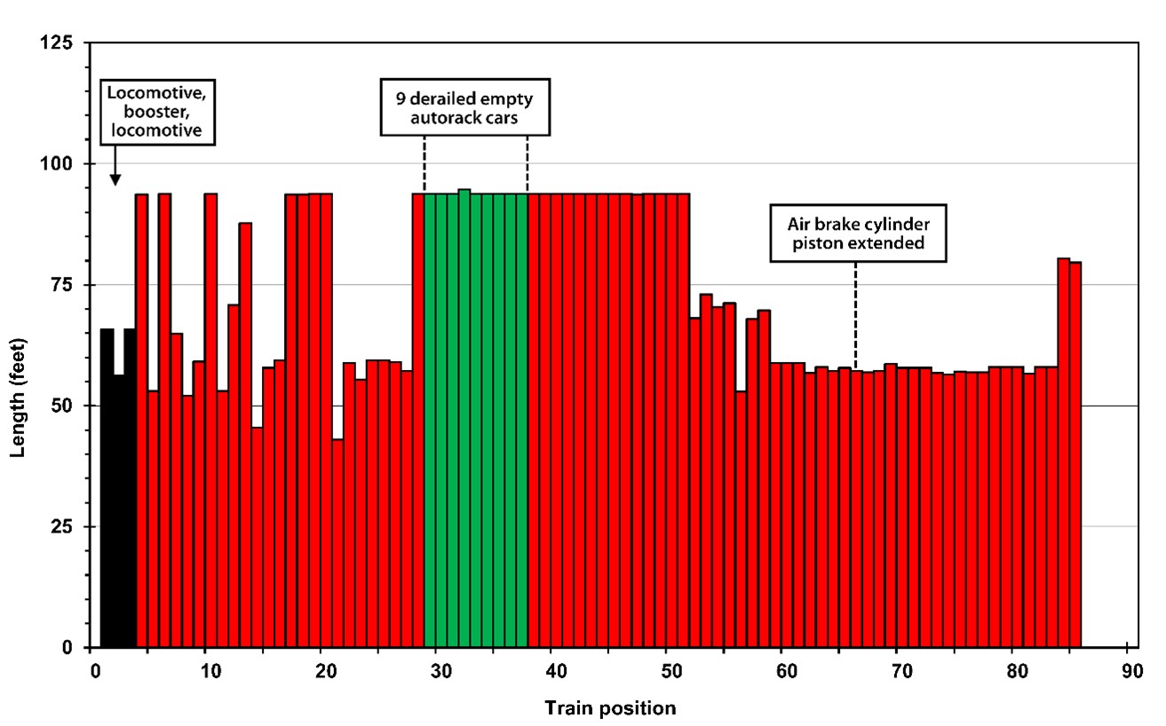
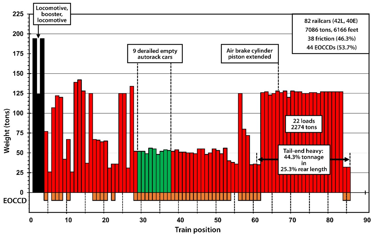
The assignment tonnage profile (Figure 15) exhibits the weight distribution throughout the assignment.
Figure 15 also illustrates how each of the 3 cuts of cars were positioned and identifies the cars equipped with EOCCDs and standard friction draft gears. In particular, the cut of heavy cars added to the rear of the assignment also contained the car in the 63rd position that was observed to have its air brake cylinder piston extended.
1.12 Ratio of lateral-to-vertical forces and potential for derailment
A combination of lateral (L) and vertical (V) forces exists at the wheel-rail interface (Figure 16). The ratio of lateral-to-vertical (L/V) forces indicates the potential for a derailment to occur. When a high lateral force and low vertical force are present (e.g., as with an empty car), the high lateral force will tend to push the wheel flange up and over the gauge face of the rail, resulting in a wheel-climb derailment.
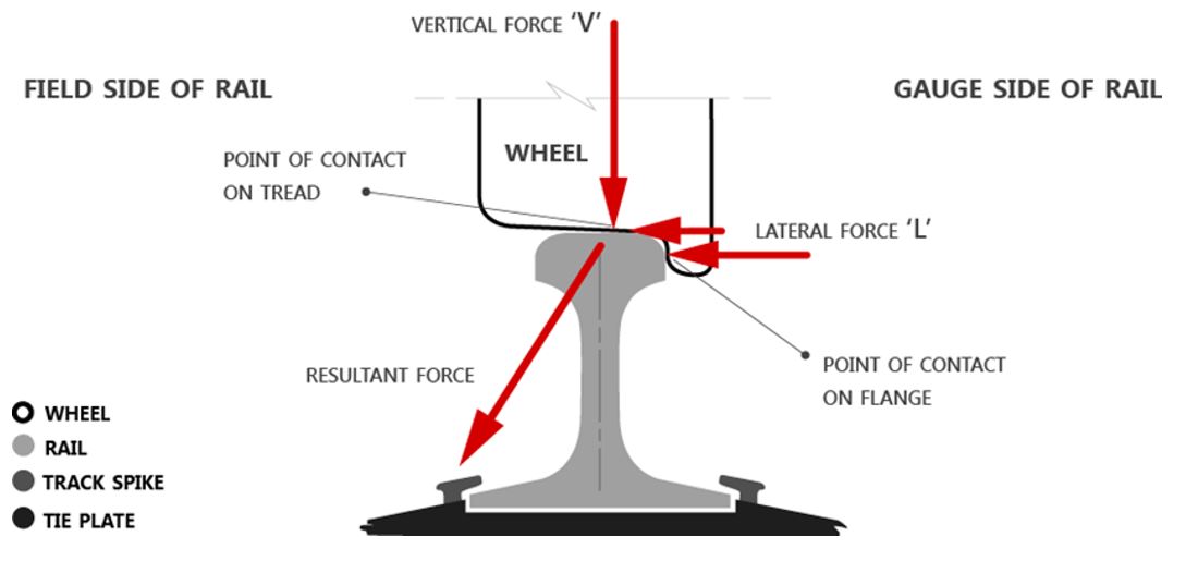
Although many factors can be involved, it is generally accepted within the industry that
- A truckside L/V ratio in excess of 0.65 is indicative of the potential for a freight car truck to roll a rail and cause a derailment.
- A single-wheel L/V ratio in excess of about 0.82 is indicative of the potential for a freight car to wheel climb (or lift) on the head of a rail and cause a derailment. This can occur within about 6 feet of movement.Footnote 19 When this happens, short wheel flange marks are often observed on the top of the low rail. Empty long cars equipped with long-travel EOCCDs, such as autorack cars and centrebeam bulkhead flat cars, are particularly vulnerable to these forces.
1.13 String-line accidents
When a train is being pulled through a curve, draft (tension) forces tend to stretch or “string-line” the train as wheel flanges are pulled taut against the inside rail of the curve. This lateral force at the rail varies directly with the locomotive tractive effort, the track grade, the degree of curvature, and coupling angles between cars. If the draft force generated by the locomotives is excessive or if there is a significant run-out of train slack, the L/V ratio can reach a critical level that results in a car wheel climbing, or lifting, onto the head of the inside rail of a curve and derailing to the field side of the low rail. Empty cars in particular can be more vulnerable in certain situations.
String-line derailments are caused by heavy draft loading, including steady-state draft loading or, more often, dynamic run-outs of slack. String-lining derailments exhibit the following characteristics:Footnote 20
- String-lining derailments happen in curves, not in tangent track.
- String-lining is often associated with excessive application of power in forward movements, and often involves the head-end cars of a train derailing after the train accelerates from a low speed in high curvature territory (classic scenario).
- Derailed cars are generally empty, lightly loaded long cars, such as autoracks and centrebeam bulkhead flat cars, or long car/short car combinations.
- Derailed cars are pulled over the low rail, usually found in a straight line, but sometimes the low rail overturns and high wheel drops in.
- Short flange marks are found on top of the low rail, or on the web/lower fillet, depending on whether the wheel climbed or the rail rolled over.
1.14 Previous string-line accidents on track W100
The derailment history of W100 was examined, and CN close-out reports from 2 similar derailments that occurred on W100 in 2012 Footnote 21 and in 2013 Footnote 22 were reviewed.
1.14.1 2012 string-line accident
On 30 May 2012, among a cut of 23 loaded cars that was added to the tail end of cars left standing on W100, there were 8 freight cars that still had air brakes applied, which presented the underlying conditions for a string-line event to occur.
A YOE was operating the assignment according to yard procedures and was pulling the cars on W100 toward the west pullback track. After the assignment had slowed for the YOE to detrain at the W100 switch, the Beltpack speed selector was returned to 15 mph and a string-line derailment occurred as 5 long empty centrebeam flat cars equipped with EOCCDs derailed to the inside of the 15-degree curve.
As a corrective action, CN implemented an inspection procedure that required the mechanical department to ensure that air brakes were released on all cars left on W100 before the cars were moved to the pullback track. However, the practice appears to have ceased sometime between May 2012 and August 2019.
1.14.2 2013 string-line accident
On 14 September 2013, a cut of long empty multi-level cars was left on W100 and a cut of loaded cars was added immediately behind. A YOE was operating the assignment according to yard procedures and was pulling the cars on W100 toward the west pullback track. The YOE decreased speed incrementally from 15 mph to 4 mph, detrained at the W100 switch, then selected a speed of 15 mph. Almost immediately after the speed was increased, 8 empty cars behind the hump set string-lined and derailed to the inside of the 15-degree curve.
Subsequently, CN issued a notice that required loaded cars left on W100 to be placed at the north end (head end) of the track. This was meant to ensure that the bulk of an assignment’s weight would be located near the head-end hump set, which would reduce the risk for a string-line event to occur.
A CN document search could not locate a record of the notice that was issued following the occurrence. Since this notice was only issued locally, and not through CN Operating Practices, the information was not carried over or included in either the next Summary Bulletin or the MacMillan Yard Operating Manual. Consequently, the practice ceased sometime between September 2013 and August 2019.
1.14.3 Railway Safety Management System Regulations (2001)
When the 2 previous string-line accidents that were similar to this accident occurred on W100 (in 2012 and 2013), the Railway Safety Management System Regulations (2001) were in force. The regulations stated (in part):
[…]
2 A railway company shall implement and maintain a safety management system that includes, at a minimum, the following components:
[…]
(e) a process for
- identifying safety issues and concerns, including those associated with human factors, third-parties and significant changes to railway operations, and
- evaluating and classifying risks by means of a risk assessment;
(f) risk control strategies;
(g) systems for accident and incident reporting, investigation, analysis and corrective action;
[…]
1.15 Dynamic simulations
Dynamic simulations are theoretical in nature and are often performed in support of derailment investigations. Simulation inputs contain a mix of recorded information (from the LER) and track engineering surveys, in conjunction with some reasonable assumptions based on experience. One of the goals for any dynamic simulation is to identify the combination of the factors/forces that produce results that most closely match the physical evidence observed on an accident site. Alternative simulations are also usually conducted to provide some clarity for potential mitigating strategies. This was the approach taken in this case.
To assist with this, the TSB contracted engineering and scientific investigation/analysis firm Engineering Systems Incorporated (ESi) to conduct a dynamic simulation using the Train Energy and Dynamics Simulator (TEDS).
The TSB site examination identified that 9 freight cars located in the 26th to 34th positions behind the locomotive hump set derailed on track W100 about 400 feet south of the W100 switch. The trailing end of the 26th car derailed to the low side of a long left-hand curve (in the direction of motion) that varied in alignment from 11 to 15 degrees. The 27th, 28th, and 29th cars remained coupled together, rolled off their trucks, separated from the head-end cars, and overturned on their side about 2 feet from the track.
The computer train dynamic simulations were conducted to examine the operations in order to better understand what factors led to the derailment. Alternative simulations using modified train handling, reduced tonnage train consists, and modified track curvature were also conducted for comparison purposes.
1.15.1 Inputs
The train dynamic simulations were conducted using the TEDS computer model to determine longitudinal coupler forces and L/V ratios using the following:
- Train handling inputs were based on the actual assignment LER recorded data. The LER data were subsequently modified to assess additional train handling scenarios.
- Track inputs were from a CN track survey conducted immediately after the accident.
- Freight car inputs were based on available occurrence car data in the Universal Machine Language Equipment Register (UMLER) database using the cars identified on the occurrence switch list. Assignment length and tonnage profiles used for the modelling were also developed from these inputs.
- The simulations assumed that there were no worn hand brake or air brake components and braking efficiency was 100%.
1.15.2 Summary of simulations and results
Seven simulations were conducted that focused on the long empty autorack cars in the 25th to the 29th positions that were involved in the accident. Simulations 1 to 3 evaluate potential causes and contributing factors while simulations 4 to 7 evaluate potential mitigation strategies. The simulation results are outlined below.
1.15.2.1 Simulation 1
The 1st simulation modeled the actual surveyed track and the actual consist with no brakes applied (rolling freely). The train handling script used the actual train handling recorded on the LER. The simulation produced the following results:
- Coupler forces were predicted to vary between almost −150 kips Footnote 23 buff to +230 kips draft on the leading autorack cars as they progressed through the 15-degree curve.
- Single-wheel L/V ratios were predicted to exceed 0.82 on multiple wheels of multiple cars and reached as high as 1.01 on the left rear wheel (low rail on the inside of the 15-degree curve) of the trailing truck of the 28th car in the consist.
- Truckside L/V ratios exceeded 0.65 on several trucks with a maximum value of 0.93 predicted on the left truckside of the trailing truck of the 28th car.
1.15.2.2 Simulation 2
The 2nd simulation modeled the actual surveyed track and the actual consist with a hand brake applied to the 63rd car. The train handling script used the actual train handling recorded on the LER. The simulation produced the following results:
- Coupler forces were predicted to be marginally different from the 1st simulation with maximum forces varying between −130 kips buff to +260 kips draft on the leading autorack cars as they progressed through the 15-degree curve.
- Single-wheel L/V ratios were predicted to approach or exceed 0.82 on multiple wheels of multiple cars. The highest single-wheel L/V ratio was 1.13 on the left rear wheel (low rail on the inside of the 15-degree curve) of the trailing truck of the 27th car.
- Truckside L/V ratios exceeded 0.65 on several trucks with a maximum value of 1.06 predicted on the left truckside of the trailing truck of the 27th car.
1.15.2.3 Simulation 3
The 3rd simulation modeled the actual surveyed track and actual consist with an emergency air brake applied to the 63rd car. The train handling script used the actual train handling recorded on the LER. The simulation produced the following results:
- Coupler forces were predicted to vary between −115 kips buff to +245 kips draft on the leading autorack cars as they progressed through the 15-degree curve.
- Single-wheel L/V ratios were predicted to approach or exceed 0.82 on multiple wheels of multiple cars.
- The highest predicted single-wheel L/V ratio was 1.14 on the left rear wheel (low rail on the inside of the 15-degree curve) of the trailing truck of the 26th car.
- Truckside L/V ratios exceeded 0.65 on several trucks with a maximum value of 1.08 predicted on the left truckside of the trailing truck of the 26th car.
1.15.2.4 Simulation 4
The 4th simulation modeled the actual surveyed track and the actual consist with no brakes applied (rolling freely). However, the train handling script was modified such that the locomotive throttle was gradually increased and limited to a maximum of notch 4. The simulation produced the following results:
- Using notch 4 to move the assignment gradually, it accelerated to a speed of about 8 to 9 mph before reaching the location where the derailment occurred. The acceleration rate to this speed was slightly slower than if the maximum notch 8 had been used, but this speed was not significantly slower than the actual speed leading up to the accident.
- Coupler buff and draft forces were significantly decreased using reduced throttle. Coupler forces were predicted to vary between −15 kips buff and +85 kips draft on the leading autorack cars as they progressed through the 15-degree curve.
- Single-wheel L/V ratios were all less than 0.50.
- Truckside L/V ratios were all predicted to be less than 0.45.
1.15.2.5 Simulation 5
The 5th simulation modeled the actual surveyed track and a reduced-tonnage consist that removed the 12 tail-end cars; this would have permitted the cars to fit in either the east or west pullback tracks, each of which is about 5600 feet long. Including the locomotives, the reduced-tonnage 70-car model had a weight of 5758 tons and a length of 5432 feet.
The reduced-tonnage consist was operated with no brakes applied (rolling freely) and the train handling script used the actual train handling recorded on the LER. The simulation produced the following results:
- Maximum coupler buff and draft forces were nearly the same as the actual assignment (simulations 1 to 3).
- Using the same train handling, the reduced-tonnage consist (5758 tons) attained a maximum speed of about 11 to 12 mph as opposed to 10 mph for the actual assignment consist (7086 tons).
- The highest single-wheel L/V ratio on the reduced-tonnage consist was 0.90 on the left rear wheel of the trailing truck of the 27th car.
- The left truckside of the trailing truck of the 27th car generated the highest maximum truckside L/V ratio of 0.82. The remaining trucksides recorded L/V ratios below the critical threshold of 0.65.
1.15.2.6 Simulation 6
The 6th simulation modeled the actual surveyed track and a reduced-tonnage consist that had the 12 tail-end cars removed. Including the locomotives, the reduced-tonnage 70-car model had a weight of 5758 tons and a length of 5432 feet and was operated with no brakes applied (rolling freely). The train handling script was modified such that the locomotive throttle was gradually increased and limited to a maximum of notch 4. The simulation produced the following results:
- A reduced-tonnage consist limited to a maximum of notch 4 accelerated to a speed of about 9 mph when it reached the derailment site.
- Coupler forces were predicted to vary between −15 kips buff and +70 kips draft on the leading autorack cars as they progressed through the 15-degree curve.
- Single-wheel L/V ratios on the leading autorack cars were not predicted to exceed 0.50.
- Truckside L/V ratios were predicted to be less than 0.40.
1.15.2.7 Simulation 7
The final (7th) simulation modeled the actual surveyed track with the exception that the accident curve was realigned and the curvature was reduced to a constant 12 degrees. The assignment model used the actual consist with no brakes applied (rolling freely) and the train handling script used the actual train handling recorded on the LER. The simulation produced the following results:
- Operating the assignment through the constant 12-degree curve using the actual train handling recorded on the LER yielded a speed that was consistent with the other comparable assignment simulations conducted. Therefore, any force and/or L/V ratio differences evident for this simulation were attributable to the revised curvature alone and not due to any appreciable operating differences.
- Coupler forces were predicted to vary between −180 kips buff force and +230 kips draft force on the leading autorack cars as they progressed through the 12-degree curve. These results were similar to the other comparable assignment simulations conducted. This would be expected as the track modification of the accident curve would not appreciably change rolling-resistive train forces.
- Single-wheel L/V ratios approached or exceeded the critical limit of 0.82 on multiple wheels of multiple cars. The highest single-wheel L/V ratio recorded was 0.88 on the right front wheel of the leading truck of the 25th car.
- Truckside L/V ratios exceeded 0.65 on several trucks with a maximum value of 0.84 predicted on the leading right truckside of the 25th car.
- Realigning and reducing the curvature of the accident curve down to a constant 12 degrees reduced L/V values in general. However, L/V values were still observed to be at or slightly above single-wheel L/V ratios of 0.82 and truckside L/V ratios of 0.65 at several positions on the 25th and 28th cars, assuming all other variables remained constant (tonnage, consist make-up, train handling, operating speeds, etc.). This suggests that despite reducing the curvature of the accident curve from 15 degrees to a constant 12 degrees, the potential for derailment would still exist if the right conditions were present.
The results of the maximum longitudinal buff and draft forces for the 24th to 29th cars recorded for each simulation are contained in Appendix C.
The results of the maximum single-wheel and truckside L/V ratios for the 24th to 29th cars for each simulation are contained in Appendix D.
1.16 Additional reports
The TSB contracted the following engineering report in support of this investigation:
- Engineering Systems Incorporated (ESi) report – Train Dynamics Simulation Analysis Derailment of CN Job YDHF60 at MacMillan Yard, 15 August 2019, performed for the Transportation Safety Board of Canada, dated 17 February 2021.
2.0 Analysis
The locomotive hump set and cars involved in the derailment were maintained in good condition. The analysis will focus on the circumstances that led to the accident which include:
- the operation of the remote control locomotive system (RCLS),
- the placement of a cut of empty vehicular flat cars (autorack cars) equipped with hydraulic end-of-car cushioning devices (EOCCD) in a vulnerable position, and
- the addition of a cut of 34 cars (3391 tons) behind the autorack cars just before the assignment commenced movement on track W100 (W100).
The analysis will also evaluate conductor training and Beltpack operation, gaps that existed in the process for ensuring that safety-critical information was carried forward, and communicating changes to freight car locations.
2.1 The accident
On 15 August 2019 at about 0045, CN 2100 west industrial yard assignment coupled a cut of 34 loaded cars to the south end of the 24 autorack cars that had previously been left standing on W100. The cut of 34 cars weighed 3391 tons and was 2074 feet long while the 24 autorack cars weighed 1245 tons and was 2252 feet long. Five minutes later, the foreman of the CN 2100 assignment informed the trainmaster by radio that they had completed the switching and the trainmaster then notified CN Car Control.
At about 0100, the occurrence assignment arrived at W100 with a cut of 24 cars from E008, that weighed 1938 tons and was 1652 feet long, and coupled onto the 58 cars standing on W100. With all cars joined together, the assignment comprised the locomotive hump set weighing 512 tons and a total of 82 freight cars weighing 6574 tons for a total combined locomotive and car weight of 7086 tons and length of 6166 feet.
At that time, unbeknownst to the yardmaster, the yardmaster trainee, and the yard operating employee (YOE), the assignment, as assembled, then had about 44% of its weight in the rear 25% of its length and therefore was significantly “tail-end heavy.”
After making the joint between the 24th and 25th cars, the YOE walked southward and released the hand brakes on the 3 autorack cars (25th car to the 27th car). Due to the location of the hand brake at the trailing end of the 27th car, in accordance with CN General Operating Instructions (GOI), the YOE had to either entrain the leading end of the following 28th car or walk back to the leading end of the 27th car about 90 feet north. Given the site observations, the YOE likely entrained the leading end of the 27th car (TTGX 995540) while the assignment was stopped, which was also in accordance with a CN system-wide bulletin that required movements to be stopped prior to operating crews entraining or detraining.
At about 0108, the assignment began to pull the entire 82 cars northward through the 15-degree left-hand curve enroute to the west pullback track.
At 0110:29, a communication failure occurred between controlling locomotive CN 6020 and the Beltpack. Following the loss of communication and as designed, the RCLS automatically placed the locomotives in idle, made a full service air brake application and applied the locomotive independent brakes on the locomotive consist.
At 0110:57, the assignment came to a stop.
The locomotive hump set and the first 26 cars came to rest coupled together with the head end positioned about 2100 feet north of the W100 switch on the west pullback track. The 26th car, empty autorack TTGX 995076, had derailed but came to rest upright. The leading A-end truck did not derail but all 4 wheels of the trailing B-end truck were derailed in the ballast on the west side of the track, just north of the W100 switch.
From the W100 switch, wheel marks were observed in the ballast extending southward for about 400 feet. These wheel marks ended near the leading end of the 27th car, where short wheel flange marks were also found on the running surface of the west rail in the exit spiral of the 15-degree curve. These flange marks were indicative of the left-side wheels of the trailing truck of the 26th car climbing the rail.
The leading A-end truck of the 27th car remained intact, did not derail and rolled along the track for about 40 feet, clear of the car. The B-end truck of the 27th car was generally intact but was impacted by the leading end of the 31st car and derailed, coming to rest on the track just ahead of the 31st car.
The 27th, 28th, and the 29th cars remained coupled together and all had rolled off their trucks and overturned on their sides on the inside of the 15-degree curve, along the track. Given the site observations, similar to the 27th car, the trucks of the 28th and 29th cars remained intact on the track until they were impacted by the trailing cars and strewn about the site as the cars derailed.
These observations were consistent with what are considered to be string-line derailment characteristics.
Finding as to causes and contributing factors
The accident occurred when the trailing end of the 26th car and the 27th to 29th cars string-lined and derailed to the inside of a 15-degree curve.
The 29th car separated from the 30th car. The 30th car overturned and came to rest on the outside of the curve, parallel to the track. The 31st to the 34th cars derailed upright and coupled together.
Finding as to causes and contributing factors
The YOE, who was riding on the left side of the overturned 27th car, was pinned beneath the leading A-end and fatally injured.
2.2 Operation of remote control locomotive system
The Beltpack is equipped with (but not limited to) a speed selector, a forward and reverse selector, and a brake selector that includes an emergency brake feature. Beltpack operators choose from a range of pre-programmed speeds: Stop, Coast, Couple (1.5 mph), Hump (2.0 mph), HumpF (fast; 2.7 mph), 4 mph, 8 mph, and Max speed (15 mph).
Assignments switching within the yard usually operate at 15 mph when practicable, unless otherwise restricted.
Once a speed is selected on the Beltpack, the RCLS manipulates the locomotive throttle to attain the selected speed. Once the selected speed is attained, the RCLS automatically controls the locomotive throttle and brakes to maintain the selected speed within a range of ±0.5 mph. The system adapts to terrain characteristics reactively, without accounting for train length, tonnage, or slack.
The RCLS operating system is programmed in such a way that the selected operating speed is attained as quickly as possible while operating within the parameters that are programmed into the RCLS to determine throttle output. When an operator increases speed on the Beltpack, the RCLS can command the remote control locomotive (RCL) consist to full throttle and may rapidly increase the RCL throttle to the maximum notch 8 position. This is in contrast to the training of locomotive engineers, who are generally prohibited from using such aggressive throttle modulation or train handling.
While the RCLS’s more aggressive throttle modulation is dependent on the differential between the current speed of the consist and the selected speed, it can also occur if the operator makes a series of small progressive speed increases or immediately selects Max speed (15 mph). Therefore, at the time of the occurrence, RCLS operators, like the occurrence YOE, did not have the ability to directly control incremental locomotive throttle changes to facilitate the slow, smooth acceleration of an assignment.
2.2.1 Recorded information
A review of recorded information from the trailing locomotive (CN 6019) locomotive event recorder (LER) and the controlling locomotive (CN 6020) operator control unit (OCU) Beltpack log revealed the following:
- At 0108:00, the Beltpack speed selector was moved to 1.5 mph (Couple) to stretch the coupling in preparation for pulling the cars from W100. Twenty-three seconds later, the RCLS ramped up to locomotive notch 4 and the assignment was travelling at 1 mph.
- At 0108:26, the assignment had not moved significantly and the Beltpack speed selector was moved to 2 mph (Hump).
- At 0108:42, the assignment had still not moved significantly and the Beltpack speed selector was moved to Max speed (15 mph) and the locomotive throttle began to increase.
- By 0108:57, the locomotive throttle had advanced to notch 8 and the speed increased to 3 mph.
- By 0109:31, the Beltpack selector had been placed in Coast.
- By 0109:35, the locomotive throttle had returned to Idle while the assignment was moving at 10 mph.
- The assignment was in “Coast” for 23 seconds. During this time, the “tail-end-heavy” assignment would have been subjected to buff forces as it bunched and decelerated to 8 mph. During this time, as identified by the dynamic simulations, the buff force was sufficient to compress the autorack EOCCDs.
- At 0109:54, the Beltpack speed selector was returned from Coast back to 15 mph. From that time until 0110:13, the RCLS advanced the locomotive throttle from Idle to notch 7, but the assignment was still travelling at 8 mph.
- At 0110:16, the RCLS advanced the locomotive throttle to notch 8 and the assignment began to accelerate.
Finding as to causes and contributing factors
Since the hydraulic EOCCDs were compressed during the previous deceleration, the acceleration of the assignment, after the locomotive throttle was advanced to notch 8, likely resulted in a rapid run-out of train slack, which contributed to the string-line derailment.
- At 0110:29, while the assignment was proceeding at 10 mph, there was a loss of communication between the Beltpack and the controlling locomotive, CN 6020.
Given the circumstances, the 26th to 29th cars likely derailed shortly after 0110:16, resulting in the loss of communication between the controlling locomotive (CN 6020) and the Beltpack OCU at 0110:29 as a result of the 27th car overturning on its side.
As demonstrated in this accident, the inability to control the slow, smooth acceleration of an assignment can be problematic and lead to string-line accidents, particularly when handling longer, tail-end-heavy assignments when negotiating a tight curve in a yard.
Finding as to causes and contributing factors
Aggressive throttle response, due to the RCLS programming that was in use at the time of the accident, led to a rapid acceleration and run-out of train slack on the long tail-end heavy assignment, which contributed to the string-lining of the autorack cars as they were exiting the 15-degree curve.
2.3 Dynamic simulations
At about 0100, the assignment arrived at W100 with the cut of 24 cars from E008. The assignment then coupled onto the 58 cars standing on W100. With all cars joined together, the assignment had a weight of 7086 tons and length of 6166 feet.
Unknown to either the yardmaster trainee or the YOE at that time, the assignment had about 44% of its weight in the rear 25% of its length and was significantly “tail-end heavy” with a relatively light cut of empty autorack cars equipped with EOCCDs located in a vulnerable position between 2 heavier cuts of cars.
According to CN’s guidance, a train marshalled like this should be prohibited from operating on a mainline. However, assignments with similar “tail-end-heavy” arrangements are allowed to operate within yards where, as demonstrated in this case and confirmed by dynamic simulations, they can still present significant risks to operating employees.
Seven different simulations were conducted in an effort to identify the combination of the factors and forces that would produce results that closely matched what was actually observed on the accident site. Alternative simulations were also conducted to provide some clarity for potential mitigating strategies.
The primary outputs for the simulations were longitudinal buff and draft forces, single-wheel lateral-to-vertical (L/V) ratios and truckside L/V ratios.
A single-wheel L/V ratio in excess of about 0.82 is indicative of the potential for a freight car wheel to climb (or lift) on the head of a rail and cause a derailment. A truckside L/V ratio in excess of 0.65 is indicative of the potential for a freight car truck to roll a rail and cause a derailment. Empty long cars equipped with long-travel EOCCDs, such as the autorack cars in this occurrence, are particularly vulnerable to these forces.
Results of the 7 simulations are summarized below in 2 general categories. Simulations 1 to 3 evaluate potential causes and contributing factors while simulations 4 to 7 evaluate potential mitigation strategies.
2.3.1 Simulations 1 to 3
Simulation 1 modeled the actual track surveyed and the actual consist with no brakes applied (rolling freely) while the train handling script used the actual train handling recorded on the LER.
During site examination after the accident, the 63rd car (DJTX 318030 loaded with scrap steel) was observed to have its brake cylinder piston extended and its brake shoes pressed against the wheels. This indicated that air brakes likely remained engaged to some degree on this car.
To see what effect brakes applied on the 63rd car may have had, the modelling for simulation 2 was the same as simulation 1 with the exception that a hand brake was applied to the 63rd car. Similarly, the modelling for simulation 3 was the same as simulation 1 with the exception that an emergency air brake application remained on the 63rd car.
Results from simulations 1 to 3 are summarized in Table 1.
| Simulation | Maximum buff force (kips) | Maximum draft force (kips) | Maximum single-wheel L/V ratio | Maximum truckside L/V ratio | Location of maximum L/V ratio |
|---|---|---|---|---|---|
| 1 (actual assignment, no brakes) | -150 | +230 | 1.01 | 0.93 |
|
| 2 (actual assignment, hand brake on 63rd car) | -130 | +260 | 1.13 | 1.06 |
|
| 3 (actual assignment, emergency air brakes on 63rd car) | -115 | +245 | 1.14 | 1.08 |
|
Simulations 1 to 3 each predicted that there was a significant potential for derailment conditions to exist with or without hand brakes or air brakes applied to the 63rd car. They also demonstrated results that far exceeded the critical thresholds for both single-wheel and truckside L/V ratios.
Finding: Other
Although the 63rd car was discovered with its brake piston extended, the dynamic forces involved, with or without brakes applied on the 63rd car, predicted a significant potential for derailment.
Finding as to causes and contributing factors
Dynamic simulations confirmed that trailing tonnage added to the tail end of the autorack cars on W100 left the assignment “tail-end heavy” with the lighter autorack cars in a vulnerable position, and caused both single-wheel and truckside L/V ratios to exceed critical thresholds.
2.3.2 Simulations 4 to 7
Results from simulations 4 to 7 are summarized in Table 2.
| Simulation | Maximum buff force (kips) | Maximum draft force (kips) | Maximum single-wheel L/V ratio | Maximum truckside L/V ratio | Location of maximum L/V ratio |
|---|---|---|---|---|---|
| 4 (reduced throttle [4]) | -15 | +85 | All less than 0.50 | All less than 0.45 | N/A |
| 5 (reduced tonnage with 12 cars removed) | -150 | +217 | 0.90 | 0.82 |
|
| 6 (reduced tonnage and throttle [4]) | -15 | +70 | All less than 0.50 | All less than 0.40 | N/A |
| 7 (reduced curvature [12 degrees]) | -180 | +230 | 0.88 | 0.84 | L/V values were still observed to be at or slightly above single-wheel L/V ratios of 0.82 and truckside L/V ratios of 0.65 at several positions on the 25th and 28th cars. |
Simulation 4 demonstrated that the most effective method to reduce the risk of derailment would be to use less aggressive train handling that limits locomotive throttle to a maximum of notch 4. Simulation 6 produced similar results even with reduced tonnage with the 12 tail-end cars removed.
Finding: Other
Dynamic simulations using less aggressive train handling predicted significantly reduced buff and draft forces with single-wheel and truckside L/V ratios well below the maximum desired threshold ratios.
Simulation 5 modeled a reduced-tonnage consist that had the 12 tail-end cars removed, which would permit it to fit in either the east or west pullback tracks.
Finding: Other
Although a dynamic simulation with reduced tonnage still produced single-wheel and truckside L/V ratios that exceeded the maximum desired threshold ratios, the predicted L/V values could be further reduced if more trailing tonnage were removed.
Simulation 7 modeled realigning and reducing the curvature of the accident curve down to a constant 12 degrees. While this reduced L/V values in general, assuming all other variables remained constant (tonnage, consist make-up, train handling, operating speeds, etc.), maximum L/V values were still observed to be at or slightly above single-wheel L/V ratios of 0.82 and truckside L/V ratios of 0.65 at several positions on the 25th and 28th cars.
Finding: Other
Results from a dynamic simulation with a curvature reduced from 15 degrees to 12 degrees showed that the potential for derailment still exists if the right conditions are present.
2.4 Combination of causal factors
Site observations and dynamic simulations have identified that a combination of factors had to be present for the specific adverse outcome of this accident to happen. Had any one of the related factors been significantly modified or removed altogether, the outcome of this accident would have been different.
Finding as to causes and contributing factors
The combined effects of the aggressive throttle response due to the RCLS programming, the vulnerable placement of empty autorack cars equipped with hydraulic EOCCDs between 2 heavier cuts of cars, and the weight of the trailing cut of 34 cars added to the assignment behind the autorack cars created the circumstances for this accident to occur.
2.5 Yard operating employee training
The YOE was qualified for his position, met fitness and rest requirements, and was familiar with the yard and hump operations. The YOE began working at CN as a conductor trainee on 18 June 2018 and was fully qualified as a conductor on 05 December 2018.
Since qualifying as a conductor, between 05 December 2018 and 15 August 2019, the YOE worked a total of 27 shifts as a YOE at the dual hump and was considered to be familiar with the tasks involved in humping operations.
Despite having only 14 months service, the YOE was considered a capable employee who was knowledgeable about the work.
2.5.1 Canadian National Railway Company Beltpack Operator Training Participant Manual
The CN Beltpack Operator Training Participant Manual discusses train handling and explains that buff, draft, vertical and lateral forces can all affect how a cut of cars will handle when moving on a track. The manual defines string-lining as the tendency of a long cut of cars to shortcut a curve when being pulled, a problem that is amplified in a heavier train when handling light cars that are followed by significant trailing tonnage. However, the training manual does not contain more specific guidance for identifying conditions that are conducive to string-lining or tips for preventing a string-line event.
Since CN assignments switching within yards operated at 15 mph when practicable, most YOEs at MacMillan Yard selected Max speed (15 mph) on the Beltpack to complete the pullback operation prior to humping. In addition, while operating within a point protection zone (PPZ), a movement is relieved of the responsibility to stop within half the range of vision.
In this occurrence, the YOE used a low speed setting to initiate the movement. Once all of the cars were moving, the OCU speed selector was moved to 15 mph, similar to the 15 mph speed selection almost always used by all CN YOEs within the hump pullback track PPZ. Therefore, the YOE’s actions were consistent with the use of Beltpack by other YOEs for similar operations that were successfully completed without any adverse consequence.
Finding: Other
The YOE’s actions while switching before the accident, and during RCLS operations using the Beltpack, were in accordance with company requirements and his training.
Although the YOE followed company training and standard company practice, dynamic simulations identified that using less aggressive OCU speed inputs is a safer option for handling the assignment.
Finding as to risk
If railways do not reinforce safe, smooth train handling options for RCLS use in yard operations and provide more specific guidance for identifying conditions that are conducive to string-line events, the risk for a string-line event will remain.
2.6 Ensuring safety-critical procedures are carried forward
As demonstrated by dynamic simulation 4, which used reduced throttle that was limited to notch 4, there are other ways to operate that could be used on track W100 to protect against similar string-line events. This was further reinforced by corrective actions taken by CN following 2 previous string-line accidents in MacMillan Yard.
After 2 similar string-line accidents that occurred on W100 in 2012 and 2013, in accordance with the Railway Safety Management System Regulations (2001) that were in force at the time, CN investigated the accidents and implemented the following corrective actions:
- In May 2012, CN implemented an inspection procedure that required the mechanical department to ensure that air brakes were released on all cars left on W100 before the cars were moved to the pullback track.
- In September 2013, CN issued a notice that required loaded cars left on W100 to be placed at the north end (head end) of the track. This was meant to ensure that the bulk of an assignment’s weight would be located near the hump set at the head end rather than at the tail end of an assignment, which would reduce the risk for a string-line event to occur. A CN document search could not locate a record of the notice. Since this notice was only issued locally, and not through CN Operating Practices, the safety-critical information was not carried forward or included in either the next Summary Bulletin or MacMillan Yard Operating Manual.
However, the only record of the corrective actions that CN implemented following the 2 previous accidents on W100 is contained in the respective CN close-out reports. Neither of the corrective actions were formally documented or carried forward as safety-critical procedures for MacMillan Yard. Consequently, both procedures ceased to be used at some point before this accident on 15 August 2019.
Not carrying forward the requirement to prohibit loaded cars on the tail end of trains on W100 eliminated a defense that could have prevented this accident.
Finding as to causes and contributing factors
Despite having implemented a safety-critical procedure to prevent string-line accidents from occurring on track W100 in response to a 2013 string-line accident, the procedure was not effectively documented or carried forward, and its use was discontinued, which likely contributed to this accident.
2.7 Communicating changes to freight car locations
At about 0050 on 15 August 2019, the foreman of the CN 2100 west industrial yard assignment advised the trainmaster by radio that they had just coupled 34 loaded cars to the south end of the empty autorack cars that occupied W100. The trainmaster then advised CN Car Control and the CN Service Reliability Strategy (SRS) system was updated to include the additional cars added to the tail end of the autorack cars on W100. However, the YOE, the yardmaster and the yardmaster trainee were not informed and were only aware that 24 empty autorack cars (1245 tons, 2252 feet long) occupied W100. The planned move was to couple the 24 cars from E008 (1938 tons, 1652 feet long) to the lead autorack car on W100 and pull the 48 cars (3183 tons, 3904 feet long) to the east pullback track in preparation for humping.
The YOE, the yardmaster and the yardmaster trainee were all unaware that there were already 58 cars on W100. Once the YOE coupled the 24 cars from E008 to the lead autorack car on W100, the assignment contained 82 freight cars, was “tail-end heavy” and 6166 feet long, which was more than 500 feet longer than the pullback tracks could handle. To fit the assignment into the west pullback track, at least 12 tail-end cars would have had to be removed from the assignment before the cars could have even been humped.
Although the CN SRS computer database is intended to identify where cars are located on any track on the CN network in North America in real time, there are gaps in the process that can result in operating crews being unaware of the number of cars that they will be switching.
Finding as to risk
If car locations in yards are not communicated to yardmasters and yard operating employees in a timely manner, operating employees may not fully comprehend the hazards associated with planned movements and the cars they are handling, which increases the risk for an accident to occur.
3.0 Findings
3.1 Findings as to causes and contributing factors
These are conditions, acts or safety deficiencies that were found to have caused or contributed to this occurrence.
- The accident occurred when the trailing end of the 26th car and the 27th to 29th cars string-lined and derailed to the inside of a 15-degree curve.
- The yard operating employee, who was riding on the left side of the overturned 27th car, was pinned beneath the leading A-end and fatally injured.
- Since the hydraulic end-of-car cushioning devices were compressed during the previous deceleration, the acceleration of the assignment, after the locomotive throttle was advanced to notch 8, likely resulted in a rapid run-out of train slack, which contributed to the string-line derailment.
- Aggressive throttle response, due to the remote control locomotive system programming that was in use at the time of the accident, led to a rapid acceleration and run-out of train slack on the long tail-end heavy assignment, which contributed to the string-lining of the autorack cars as they were exiting the 15-degree curve.
- Dynamic simulations confirmed that trailing tonnage added to the tail end of the autorack cars on track W100 left the assignment “tail-end heavy” with the lighter autorack cars in a vulnerable position, and caused both single-wheel and truckside lateral to vertical (L/V) ratios to exceed critical thresholds.
- The combined effects of the aggressive throttle response due to the remote control locomotive system programming, the vulnerable placement of empty autorack cars equipped with hydraulic end-of-car cushioning devices between 2 heavier cuts of cars, and the weight of the trailing cut of 34 cars added to the assignment behind the autorack cars created the circumstances for this accident to occur.
- Despite having implemented a safety-critical procedure to prevent string-line accidents from occurring on track W100 in response to a 2013 string-line accident, the procedure was not effectively documented or carried forward, and its use was discontinued, which likely contributed to this accident.
3.2 Findings as to risk
These are conditions, unsafe acts or safety deficiencies that were found not to be a factor in this occurrence but could have adverse consequences in future occurrences.
- If railways do not reinforce safe, smooth train handling options for remote control locomotive systems use in yard operations and provide more specific guidance for identifying conditions that are conducive to string-line events, the risk for a string-line event will remain.
- If car locations in yards are not communicated to yardmasters and yard operating employees in a timely manner, operating employees may not fully comprehend the hazards associated with planned movements and the cars they are handling, which increases the risk for an accident to occur.
3.3 Other findings
These items could enhance safety, resolve an issue of controversy, or provide a data point for future safety studies.
- Although the 63rd car was discovered with its brake piston extended, the dynamic forces involved, with or without brakes applied on the 63rd car, predicted a significant potential for derailment.
- Dynamic simulations using less aggressive train handling predicted significantly reduced buff and draft forces with single-wheel and truckside lateral-to-vertical (L/V) ratios well below the maximum desired threshold ratios.
- Although a dynamic simulation with reduced tonnage still produced single-wheel and truckside lateral-to-vertical (L/V) ratios that exceeded the maximum desired threshold ratios, the predicted L/V values could be further reduced if more trailing tonnage were removed.
- Results from a dynamic simulation with a curvature reduced from 15 degrees to 12 degrees showed that the potential for derailment still exists if the right conditions are present.
- The yard operating employee’s actions while switching before the accident, and during the remote control locomotive system operations using the Beltpack, were in accordance with company requirements and his training.
4.0 Safety action
4.1 Safety action taken
4.1.1 Transport Canada
Transport Canada (TC) undertook an investigation under the Canada Labour Code, Part II (CLC II), and as a result, 2 directions were issued to the Canadian National Railway Company (CN): one on 15 August 2019, and another one on 11 October 2019.
TC reviewed the corrective measures implemented by CN and deemed them to be satisfactory.
The CLC II investigation has been completed and the results shared with the employer and its workplace health and safety committee as per CLC II requirements.
4.1.2 Canadian National Railway Company
4.1.2.1 S-Yard industrial pulls
On 15 August 2019, CN issued Notice No. 1908-15, which contained revised instructions for S-Yard industrial released cars. The notice identified that effective immediately and until otherwise notified:
- All loaded releases from S-Yard (S031/S032) and the metal distribution centre (W109/W110) must not be positioned on track W100 to be humped at the dual hump.
- The cars on W100 track (W100) will be pulled by itself (i.e., cars are not to be doubled from other tracks to W100 to be humped).
- Movements from W100 onto the west pullback are not to exceed 8 mph.
4.1.2.2 Revised instructions for pulling cars on W100 track
On 21 August 2019, CN issued Notice No. 1908-21, which contained revised instructions for pulling W100 and S-Yard industrial released cars. The notice identified that the instructions were effective immediately and until otherwise notified.
4.1.2.2.1 Additional new instructions
Due to the high-degree curvature at the north end of W100, CN eliminated the need to stop and restart movements to detrain at the W100 switch in order to eliminate in-train forces and the potential for derailment in these curves. The new procedure requires that:
- the yard operating employee (YOE) release the hand brakes on W100 then cross over to the south-east side of the track, being mindful of potential movements on the diesel shop inbound and outbound tracks;
- the northward pull commence only after the YOE has walked eastward to a point ahead of the locomotive consist and maintains at least a 50-foot distance from the W100 lead while cars are being pulled; and
- the entire cut of cars from W100 pass the crossing before the YOE walks up to line the W100 switch for the west pullback toward the crest.
4.1.2.2.2 Train handling while pulling cars from W100 track
Once movement has commenced and has been ramped up to the 8 mph speed selector position (the maximum allowed speed to pull cars from W100 onto the west pullback), except in case of emergency, the throttle selector lever should only be placed to the “Coast” position to bring the movement to a stop.
- Do not ramp down from 8 mph to another speed position, and
- The locomotive independent brake selector should not be used at all.
The instructions previously communicated in Notice No. 1908-15 for the S-Yard industrial released cars remained in effect.
4.1.2.3 Other Canadian National Railway Company corrective measures
CN has also implemented the following corrective measures:
- Training material has been updated to
- Highlight hazard areas for tracks with high curvature.
- Instruct CN employees to ride either the locomotive or trailing car on tracks with curves of over 12 degrees.
- The 15-degree left-hand curve on W100 has been reconfigured to reduce the track’s curvature from 15 degrees to 12 degrees.
- A process was developed to verify that safety-critical information communicated by a notice is also included in the next Summary Bulletin and, if required, the respective yard operating manual.
- Working with General Electric and Beltpack manufacturer Cattron Intellectual Property Corporation, changes were made to remote control locomotive systems (RCLS) programming to allow for a more gradual application of the locomotive throttle during RCLS operations.
This report concludes the Transportation Safety Board of Canada’s investigation into this occurrence. The Board authorized the release of this report on . It was first released on .
Correction
After the publication of this report on 05 April 2022, the TSB was provided with additional information related to the Analysis and Findings sections. As a result, the TSB reviewed the report and concluded that the investigation could not confirm which car, from cars 26 to 29, derailed first in a string-lined fashion. Revisions were made to the report to highlight this.
Simulations 1 to 3 all showed high predicted lateral/vertical (L/V) ratios on cars 26 to 29. Taking into consideration that Train Energy and Dynamics Simulator (TEDS) simulations provide theoretical calculations of forces that can be used to estimate L/V ratios, the investigation could not confirm that the trailing end of car 26 was the first to derail. However, the calculations and evidence collected confirm that the trailing end of car 26 string-lined and derailed along with cars 27 to 29 and the conductor was pinned under car 27 on the inside of the 15-degree curve. Consequently, sections 1.3 (Site examination), 1.15 (Dynamic simulations), 1.15.2.3 (Simulation 3), 2.1 (The accident), 2.2.1 (Recorded information), 2.3.1 (Simulations 1 to 3), and 3.1 (Findings as to causes and contributing factors) were amended to reflect that information.
Additionally, Section 2.3.1.1 (Effect of brakes applied to 63rd car) was deleted in order to remove the residual air brake as a contributing factor in the accident because the investigation could not determine the amount of brake force present on the car after it had been left stationary for 46 hours. Although the 63rd car was discovered with its brake piston extended, the dynamic forces involved, with or without brakes applied on the 63rd car, predicted a significant potential for derailment. Amendments were also made to sections 1.7.2 (Beltpack Operator Training Participant Manual), 2.4 (Combination of causal factors), 2.5.1 (Canadian National Railway Company Beltpack Operator Training Participant Manual), 2.6 (Ensuring safety-critical procedures are carried forward), 3.1 (Findings as to causes and contributing factors), and 3.3 (Other findings) as a result of that change.
Further, the Executive summary was reviewed and modified to match the changes made to the final report.
This correction was approved by the Board on ; the corrected version of the report was released on .
Appendices
Appendix A – Assignment consist
| Line in consist | Car number | Length (feet) | Weight (tons) | Association of American Railroads car type | Coupler type | Coupler length (inches) | End-of-car cushioning device travel (inches) | Estimated truck center spacing (feet) |
|---|---|---|---|---|---|---|---|---|
| 0.1 | CN 6020 | 65.8 | 194 | SD-40 locomotive | N/A | N/A | N/A | N/A |
| 0.2 | CN 232 | 56.2 | 124 | Yard booster | N/A | N/A | N/A | N/A |
| 0.3 | CN 6019 | 65.8 | 194 | SD-40 locomotive | N/A | N/A | N/A | N/A |
| 1 | ETTX 802338 | 93.7 | 77 | Vehicular flat car | E69 | 60.0 | 10 | 70.3 |
| 2 | DJJX 950873 | 53.1 | 26 | GT gondola car | E60 | 28.5 | N/A | 39.8 |
| 3 | CN 668139 | 93.8 | 107 | Flat car | E69 | 60.0 | 10 | 70.4 |
| 4 | ARMN 902141 | 64.9 | 122 | Refrigerator car | E60 | 28.5 | 20 | 43.3 |
| 5 | MBKX 250298 | 52.1 | 120 | Equipped gondola | E60 | 28.5 | 15 | 39.1 |
| 6 | SHQX 9526 | 59.2 | 42 | Tank car | E60 | 28.5 | N/A | 44.4 |
| 7 | TTGX 693526 | 93.8 | 67 | Vehicular flat car | E69 | 60.0 | 10 | 70.4 |
| 8 | UFTX 20017 | 53.1 | 26 | Equipped gondola | E60 | 28.5 | N/A | 39.8 |
| 9 | ATW 400563 | 70.8 | 139 | Unequipped gondola | E68 | 43.0 | N/A | 53.1 |
| 10 | CN 48974 | 87.8 | 142 | Maintenance-of-way | E68 | 43.0 | N/A | 65.8 |
| 11 | OFOX 60869 | 45.4 | 128 | Covered hopper car | E60 | 28.5 | N/A | 31.3 |
| 12 | DLRX 520021 | 57.8 | 37 | Equipped gondola | E60 | 28.5 | N/A | 43.4 |
| 13 | UTLX 211030 | 59.3 | 125 | Tank car | E60 | 28.5 | N/A | 44.5 |
| 14 | TTGX 971983 | 93.7 | 67 | Vehicular flat car | E69 | 60.0 | 10 | 70.3 |
| 15 | TTGX 978174 | 93.7 | 66 | Vehicular flat car | E69 | 60.0 | 10 | 70.3 |
| 16 | TTGX 704952 | 93.8 | 64 | Vehicular flat car | E69 | 60.0 | 10 | 70.4 |
| 17 | TTGX 704952 | 93.8 | 65 | Vehicular flat car | E69 | 60.0 | 10 | 70.4 |
| 18 | UTLX 65730 | 43.0 | 31 | Tank car | E60 | 28.5 | N/A | 32.3 |
| 19 | TR 86305 | 58.9 | 36 | Equipped box car | E60 | 28.5 | 15 | 44.2 |
| 20 | UTLX 670329 | 55.4 | 36 | Tank car | E60 | 28.5 | N/A | 41.6 |
| 21 | SHPX 222517 | 59.3 | 125 | Tank car | E60 | 28.5 | N/A | 44.5 |
| 22 | SHPX 222386 | 59.3 | 125 | Tank car | E60 | 28.5 | N/A | 44.5 |
| 23 | CN 110732 | 59.0 | 31 | Covered hopper car | E60 | 28.5 | N/A | 44.3 |
| 24 | NOKL 320202 | 57.2 | 134 | Equipped gondola | E60 | 28.5 | N/A | 42.9 |
| 25 | TTGX 996790 | 93.8 | 52 | Vehicular flat car | E69 | 60.0 | 10 | 70.4 |
| 26 | TTGX 995076 (derailed) | 93.8 | 52 | Vehicular flat car | E69 | 60.0 | 10 | 66.0 |
| 27 | TTGX 995540 (derailed) | 93.8 | 52 | Vehicular flat car | E69 | 60.0 | 10 | 70.4 |
| 28 | TTGX 697632 (derailed) | 93.8 | 49 | Vehicular flat car | E69 | 60.0 | 10 | 70.4 |
| 29 | CTTX 691364 (derailed) | 93.8 | 52 | Vehicular flat car | E69 | 60.0 | 10 | 70.4 |
| 30 | TTGX 922201 (derailed) | 94.7 | 56 | Vehicular flat car | E69 | 60.0 | 10 | 70.4 |
| 31 | TTGX 982102 (derailed) | 93.8 | 55 | Vehicular flat car | E69 | 60.0 | 10 | 70.4 |
| 32 | CN 704642 (derailed) | 93.8 | 48 | Vehicular flat car | E69 | 60.0 | 10 | 70.4 |
| 33 | CN 704288 (derailed) | 93.8 | 54 | Vehicular flat car | E69 | 60.0 | 10 | 70.4 |
| 34 | TTGX 965970 (derailed) | 93.8 | 53 | Vehicular flat car | E69 | 60.0 | 10 | 70.4 |
| 35 | TTGX 994291 | 93.8 | 52 | Vehicular flat car | E69 | 60.0 | 10 | 70.4 |
| 36 | CTTX 692688 | 93.8 | 54 | Vehicular flat car | E69 | 60.0 | 10 | 70.4 |
| 37 | TTGX 953697 | 93.8 | 51 | Vehicular flat car | E69 | 60.0 | 10 | 70.4 |
| 38 | KCS 8688 | 93.8 | 51 | Vehicular flat car | E69 | 60.0 | 10 | 70.4 |
| 39 | BNSF 301247 | 93.8 | 50 | Vehicular flat car | E69 | 60.0 | 10 | 70.4 |
| 40 | NKCR 7583 | 93.8 | 50 | Vehicular flat car | E69 | 60.0 | 10 | 70.4 |
| 41 | TTGX 696834 | 93.8 | 49 | Vehicular flat car | E69 | 60.0 | 10 | 70.4 |
| 42 | TTGX 973991 | 93.8 | 55 | Vehicular flat car | E69 | 60.0 | 10 | 70.4 |
| 43 | TTGX 990478 | 93.8 | 55 | Vehicular flat car | E69 | 60.0 | 10 | 70.4 |
| 44 | NS 171683 | 93.7 | 48 | Vehicular flat car | E69 | 60.0 | 10 | 70.3 |
| 45 | KCS 8750 | 93.8 | 50 | Vehicular flat car | E69 | 60.0 | 10 | 70.4 |
| 46 | TTGX 982199 | 93.8 | 55 | Vehicular flat car | E69 | 60.0 | 10 | 70.4 |
| 47 | TTGX 965704 | 93.8 | 53 | Vehicular flat car | E69 | 60.0 | 10 | 70.4 |
| 48 | TTGX 694744 | 93.8 | 49 | Vehicular flat car | E69 | 60.0 | 10 | 70.4 |
| 49 | UP 961356 | 68.1 | 56 | Equipped box car | E68 | 43.0 | 18 | 51.1 |
| 50 | LW 62160 | 73.0 | 40 | Flat car | E68 | 43.0 | 15 | 48.1 |
| 51 | CIGX 805097 | 70.4 | 38 | Equipped gondola | E68 | 43.0 | N/A | 55.8 |
| 52 | IC 3702 | 71.2 | 36 | Unequipped gondola | E68 | 43.0 | N/A | 53.4 |
| 53 | SMW 380543 | 52.9 | 125 | Equipped gondola | E60 | 28.5 | 14 | 39.7 |
| 54 | WC 22209 | 67.9 | 80 | Equipped box car | E68 | 43.0 | 15 | 46.3 |
| 55 | TFM 20024 | 69.7 | 72 | Equipped box car | E68 | 43.0 | 15 | 52.3 |
| 56 | AOK 473347 | 58.9 | 35 | Equipped box car | E60 | 28.5 | 15 | 44.2 |
| 57 | TR 86239 | 58.9 | 36 | Equipped box car | E60 | 28.5 | 15 | 44.2 |
| 58 | AOK 473319 | 58.9 | 35 | Equipped box car | E60 | 28.5 | 15 | 44.2 |
| 59 | CN 135305 | 56.8 | 126 | Equipped gondola | E60 | 28.5 | N/A | 43.9 |
| 60 | WC 54066 | 58.0 | 127 | Equipped gondola | E60 | 28.5 | N/A | 43.5 |
| 61 | DJJX 315816 | 57.2 | 123 | Equipped gondola | E60 | 28.5 | N/A | 42.9 |
| 62 | DJJX 3175 | 57.8 | 125 | Equipped gondola | E60 | 28.5 | N/A | 43.4 |
| 63 | DJTX 318030 (air brake cylinder piston extended) | 57.2 | 128 | Equipped gondola | E60 | 28.5 | N/A | 42.9 |
| 64 | DJJX 19293 | 56.9 | 126 | Equipped gondola | E60 | 28.5 | N/A | 42.7 |
| 65 | DJTX 318161 | 57.2 | 128 | Equipped gondola | E60 | 28.5 | N/A | 42.9 |
| 66 | TFOX 3301 | 58.6 | 120 | GT gondola car | E60 | 28.5 | N/A | 43.9 |
| 67 | OMNX 1205 | 57.8 | 128 | Unequipped gondola | E60 | 28.5 | N/A | 43.4 |
| 68 | OMNX 597 | 57.8 | 127 | Unequipped gondola | E60 | 28.5 | N/A | 43.7 |
| 69 | OMNX 572 | 57.8 | 127 | Unequipped gondola | E60 | 28.5 | N/A | 43.4 |
| 70 | CN 135207 | 56.8 | 125 | Equipped gondola | E60 | 28.5 | N/A | 42.6 |
| 71 | IC 245902 | 56.4 | 125 | Equipped gondola | E60 | 28.5 | N/A | 42.3 |
| 72 | DJJX 19335 | 57.1 | 126 | Equipped gondola | E60 | 28.5 | N/A | 42.8 |
| 73 | DJJX 19324 | 56.9 | 126 | Equipped gondola | E60 | 28.5 | N/A | 42.7 |
| 74 | DJJX 19280 | 56.9 | 125 | Equipped gondola | E60 | 28.5 | N/A | 42.7 |
| 75 | WC 54137 | 58.0 | 127 | Equipped gondola | E60 | 28.5 | N/A | 43.5 |
| 76 | WC 54210 | 58.0 | 127 | Equipped gondola | E60 | 28.5 | N/A | 43.5 |
| 77 | WC 54174 | 58.0 | 127 | Equipped gondola | E60 | 28.5 | N/A | 43.5 |
| 78 | BLE 30122 | 56.6 | 127 | Equipped gondola | E60 | 28.5 | N/A | 42.4 |
| 79 | WC 54163 | 58.0 | 127 | Equipped gondola | E60 | 28.5 | N/A | 43.5 |
| 80 | WC 54225 | 58.0 | 127 | Equipped gondola | E60 | 28.5 | N/A | 43.5 |
| 81 | NOKL 734507 | 80.4 | 32 | Flat car | E68 | 43.0 | 10 | 60.3 |
| 82 | DWC 627570 | 79.6 | 32 | Flat car | E68 | 43.0 | 10 | 59.7 |
| Total | 6166 | 7086 | ||||||
Appendix B – Recorded information
| Event | Time (hm:s) | Distance traveled (feet) | Speed (mph) | BPP* (psi) | BCP** (psi) | LER throttle | OCU*** command |
|---|---|---|---|---|---|---|---|
| Speed command | 0106:51 | 0 | 0 | 88 | 66 | Idle | Stop |
| Idle | 0106:56 | 0 | 1 | 88 | 66 | Idle | N/A |
| Couple and stop | 0106:59 | 0 | 0 | 88 | 66 | Idle | N/A |
| Speed command | 0108:00 | N/A | N/A | N/A | N/A | N/A | 1.50 mph - Couple |
| T3 | 0108:02 | 0 | 0 | 88 | 66 | 3 | N/A |
| T4 | 0108:23 | 53 | 1 | 88 | 0 | 4 | N/A |
| Speed command | 0108:26 | N/A | N/A | N/A | N/A | N/A | 2 mph - Hump |
| Speed command | 0108:42 | N/A | N/A | N/A | N/A | N/A | 15 |
| T5 | 0108:47 | 53 | 2 | 88 | 0 | 5 | N/A |
| T6 | 0108:51 | 106 | 2 | 88 | 0 | 6 | N/A |
| T7 | 0108:54 | 106 | 2 | 88 | 0 | 7 | N/A |
| Speed command | 0108:55 | N/A | N/A | N/A | N/A | N/A | 15 |
| T8 | 0108:57 | 106 | 3 | 88 | 0 | 8 | N/A |
| Odometer reset | 0109:30 | N/A | N/A | N/A | N/A | N/A | 8 |
| Speed command | 0109:30 | N/A | N/A | N/A | N/A | N/A | 1.50 mph -Couple |
| Speed command | 0109:31 | N/A | N/A | N/A | N/A | N/A | Coast*** |
| T1 | 0109:32 | 475 | 10 | 88 | 0 | 1 | N/A |
| Idle | 0109:35 | 528 | 10 | 88 | 0 | Idle | N/A |
| Speed command | 0109:54 | N/A | N/A | N/A | N/A | N/A | 15 |
| T3 | 0109:56 | 792 | 8 | 88 | 0 | 3 | N/A |
| T4 | 0110:03 | 845 | 8 | 88 | 0 | 4 | N/A |
| T5 | 0110:06 | 898 | 8 | 88 | 0 | 5 | N/A |
| T6 | 0110:10 | 950 | 8 | 88 | 0 | 6 | N/A |
| T7 | 0110:13 | 950 | 8 | 88 | 0 | 7 | N/A |
| T8 | 0110:16 | 1003 | 9 | 88 | 0 | 8 | N/A |
| T8 (likely event) | 0110:19 | 1043 | 9 | 88 | 0 | 8 | N/A |
| Loss of communication between OCU and CN 6020 | 0110:29 | 1166 | 10 | 88 | 0 | 8 | 15 |
| Transition from notch 8 to Idle that automatically occurs after a loss of communication | 0110:30 | N/A | N/A | N/A | N/A | N/A | 15 |
| Idle | 0110:31 | 1219 | 11 | 88 | 0 | Idle | N/A |
| Full service air brake application initiates automatically | 0110:35 | 1267 | 11 | 86 | 0 | Idle | N/A |
| Independent brake application | 0110:36 | 1267 | 11 | 84 | 5 | Idle | N/A |
| BCP build-up as air brakes automatically apply | 0110:37 | 1320 | 11 | 82 | 10 | Idle | N/A |
| BCP 15 psi | 0110:38 | 1320 | 10 | 82 | 15 | Idle | N/A |
| BCP 20 psi | 0110:39 | 1320 | 10 | 80 | 20 | Idle | N/A |
| BCP 25 psi | 0110:41 | 1373 | 9 | 78 | 25 | Idle | N/A |
| BCP 31 psi | 0110:41 | 1373 | 9 | 76 | 31 | Idle | N/A |
| BCP 36 psi | 0110:42 | 1373 | 9 | 76 | 36 | Idle | N/A |
| BCP 41 psi | 0110:43 | 1373 | 8 | 75 | 41 | Idle | N/A |
| BCP 46 psi | 0110:44 | 1373 | 8 | 75 | 46 | Idle | N/A |
| BCP 51 psi | 0110:44 | 1373 | 8 | 73 | 51 | Idle | N/A |
| BCP 56 psi | 0110:45 | 1426 | 8 | 73 | 56 | Idle | N/A |
| BCP 61 psi | 0110:46 | 1426 | 7 | 71 | 61 | Idle | N/A |
| BCP 67 psi | 0110:47 | 1426 | 7 | 69 | 67 | Idle | N/A |
| BCP 72 psi | 0110:47 | 1426 | 7 | 69 | 72 | Idle | N/A |
| BCP 77 psi | 0110:48 | 1426 | 6 | 67 | 77 | Idle | N/A |
| Max independent brake | 0110:49 | 1426 | 5 | 67 | 82 | Idle | N/A |
| Stop | 0110:57 | 1478 | 0 | 55 | 82 | Idle | N/A |
* BPP: brake pipe pressure
** BCP: brake cylinder pressure
*** Coast: This generally means to coast with no throttle or brake applied by the operator. However, the system has the ability to automatically apply brakes as necessary in order to maintain selected speed, when accelerating due to train action or on a descending grade. If the remote control locomotive system (RCLS) is left in the Coast setting, the movement will eventually coast to a stop because as the speed decreases, the lower speed becomes the maximum speed that the RCLS will permit without applying brakes.
**** OCU: operator control unit
Appendix C – Maximum buff and draft forces for the 24th to 29th cars for all simulations
| Consist | Track and handling | Force type | Maximum forces on listed vehicle (kips) | ||||||
|---|---|---|---|---|---|---|---|---|---|
| Entire train (vehicle) | Vehicle 27 (car 24) | Vehicle 28 (car 25) | Vehicle 29 (car 26) | Vehicle 30 (car 27) | Vehicle 31 (car 28) | Vehicle 32 (car 29) | |||
| Incident train: 2 locomotives, 1 slug, 82 cars, 6574 tons | Actual track: Actual handling based on event recorder | Draft | 240 (3) | 228 | 229 | 230 | 231 | 231 | 231 |
| Buff | −207 (62) | −125 | −133 | −136 | −139 | −143 | −146 | ||
| Incident train: 2 locomotives, 1 slug, 82 cars, 6574 tons | Actual track: Actual handling based on event recorder with 1 hand brake applied on vehicle 66 (63rd car) | Draft | 275 (17) | 261 | 259 | 257 | 255 | 253 | 249 |
| Buff | −181 (61) | −111 | −119 | −122 | −124 | −127 | −129 | ||
| Incident train: 2 locomotives, 1 slug, 82 cars, 6574 tons | Actual track: Actual handling based on event recorder with vehicle 66 (63rd car) in emergency | Draft | 257 (13) | 247 | 245 | 244 | 244 | 246 | 246 |
| Buff | −138 (67) | −95 | −115 | −109 | −112 | −109 | −108 | ||
| Incident train: 2 locomotives, 1 slug, 82 cars, 6574 tons | Actual track: Gradual throttling up to RUN 4 maximum | Draft | 117 (3) | 81 | 81 | 81 | 81 | 81 | 82 |
| Buff | −21 (2) | −8 | −11 | −4 | −3 | 0 | 0 | ||
| Reduced-tonnage train: 2 locomotives, 1 slug, 67 cars, 5246 tons | Actual track: Actual handling based on event recorder | Draft | 227 (17) | 216 | 216 | 216 | 216 | 217 | 217 |
| Buff | −168 (51) | −129 | −139 | −143 | −147 | −150 | −153 | ||
| Reduced-tonnage train: 2 locomotives, 1 slug, 67 cars, 5246 tons | Actual track: Gradual throttling up to RUN 4 maximum | Draft | 109 (3) | 70 | 69 | 69 | 69 | 68 | 67 |
| Buff | −20 (51) | −8 | −11 | −4 | −3 | 0 | 0 | ||
| Incident train: 2 locomotives, 1 slug, 82 cars, 6574 tons | Incident curve reduced to 12 degrees: Actual handling based on event recorder | Draft | 249 (15) | 228 | 222 | 223 | 224 | 224 | 223 |
| Buff | −195 (55) | −141 | −160 | −165 | −173 | −175 | −177 | ||
Source: TSB, based on data from Engineering Systems Incorporated
Appendix D – Maximum lateral-to-vertical (L/V) ratios for the 24th to 29th cars for all simulations
| Consist | Handling | Vehicle (car) | Leading truck | Trailing truck | ||||||||||
|---|---|---|---|---|---|---|---|---|---|---|---|---|---|---|
| Front left wheel | Front right wheel | Rear left wheel | Rear right wheel | Truckside left | Truckside right | Front left wheel | Front right wheel | Rear left wheel | Rear right wheel | Truckside left | Truckside right | |||
| Incident train: 2 locomotives, 1 slug, 82 cars, 6574 tons | Actual track: Actual handling based on event recorder | 27 (24) | 0.35 | 0.42 | 0.29 | 0.18 | 0.32 | 0.30 | 0.35 | 0.45 | 0.21 | 0.12 | 0.28 | 0.29 |
| 28 (25) | 0.52 | 0.86 | 0.79 | 0.66 | 0.66 | 0.76 | 0.52 | 0.58 | 0.65 | 0.28 | 0.58 | 0.43 | ||
| 29 (26) | 0.39 | 0.77 | 0.60 | 0.59 | 0.50 | 0.68 | 0.52 | 0.62 | 0.66 | 0.51 | 0.59 | 0.57 | ||
| 30 (27) | 0.57 | 0.68 | 0.87 | 0.39 | 0.72 | 0.54 | 0.71 | 0.56 | 0.89 | 0.29 | 0.80 | 0.41 | ||
| 31 (28) | 0.72 | −0.81 | 0.92 | 0.55 | 0.82 | 0.63 | 0.84 | 0.62 | 1.01 | 0.59 | 0.93 | 0.60 | ||
| 32 (29) | 0.52 | 0.58 | 0.77 | −0.22 | 0.65 | 0.40 | 0.35 | 0.45 | 0.14 | 0.07 | 0.24 | 0.25 | ||
| Incident train: 2 locomotives, 1 slug, 82 cars, 6574 tons | Actual track: Actual handling based on event recorder with 1 hand brake applied on vehicle 66 (63rd car) | 27 (24) | 0.35 | 0.42 | 0.29 | 0.18 | 0.32 | 0.30 | 0.35 | 0.44 | 0.19 | 0.11 | 0.27 | 0.28 |
| 28 (25) | 0.50 | 0.78 | 0.77 | 0.52 | 0.64 | 0.65 | 0.51 | 0.56 | 0.64 | 0.22 | 0.58 | 0.39 | ||
| 29 (26) | 0.52 | 0.74 | 0.77 | 0.51 | 0.65 | 0.62 | 0.59 | 0.61 | 0.76 | 0.47 | 0.68 | 0.55 | ||
| 30 (27) | 0.79 | −0.83 | 1.12 | 0.30 | 0.93 | −0.53 | 0.98 | 0.52 | 1.13 | 0.16 | 1.06 | 0.34 | ||
| 31 (28) | 0.42 | 0.69 | 0.70 | 0.50 | 0.57 | 0.59 | 0.59 | 0.61 | 0.76 | 0.56 | 0.68 | 0.59 | ||
| 32 (29) | 0.69 | −0.77 | 0.91 | −0.23 | 0.80 | −0.54 | 0.35 | 0.45 | 0.14 | 0.07 | 0.24 | 0.25 | ||
| Incident train: 2 locomotives, 1 slug, 82 cars, 6574 tons | Actual track: Actual handling based on event recorder with vehicle 66 (63rd car) in emergency | 27 (24) | 0.35 | 0.42 | 0.29 | 0.18 | 0.32 | 0.30 | 0.35 | 0.45 | 0.18 | 0.12 | 0.26 | 0.29 |
| 28 (25) | 0.55 | 0.64 | 0.82 | 0.25 | 0.69 | 0.45 | 0.54 | 0.58 | 0.68 | 0.30 | 0.62 | 0.43 | ||
| 29 (26) | 0.82 | −0.95 | 1.10 | 0.37 | 0.95 | −0.62 | 1.00 | 0.62 | 1.14 | 0.53 | 1.08 | 0.58 | ||
| 30 (27) | 0.50 | −0.58 | 0.76 | −0.19 | 0.64 | −0.42 | 0.60 | 0.51 | 0.75 | 0.20 | 0.68 | 0.35 | ||
| 31 (28) | 0.75 | −0.76 | 0.98 | 0.34 | 0.87 | −0.50 | 0.88 | 0.59 | 1.03 | 0.53 | 0.95 | 0.56 | ||
| 32 (29) | 0.44 | 0.60 | 0.68 | −0.20 | 0.56 | 0.40 | 0.35 | 0.44 | 0.15 | 0.07 | 0.25 | 0.25 | ||
| Incident train: 2 locomotives, 1 slug, 82 cars, 6574 tons | Actual track: Gradual throttling up to RUN 4 maximum | 27 (24) | 0.35 | 0.42 | 0.29 | 0.18 | 0.32 | 0.30 | 0.35 | 0.42 | 0.20 | 0.09 | 0.27 | 0.26 |
| 28 (25) | 0.37 | 0.45 | 0.53 | −0.13 | 0.45 | 0.25 | 0.35 | 0.47 | 0.40 | 0.11 | 0.38 | 0.26 | ||
| 29 (26) | 0.35 | 0.49 | 0.43 | −0.11 | 0.39 | 0.29 | 0.35 | 0.47 | 0.40 | 0.11 | 0.38 | 0.27 | ||
| 30 (27) | 0.35 | 0.49 | 0.43 | −0.12 | 0.39 | 0.28 | 0.39 | 0.47 | 0.45 | −0.11 | 0.42 | 0.27 | ||
| 31 (28) | 0.35 | 0.49 | 0.39 | −0.11 | 0.37 | 0.29 | 0.35 | 0.46 | 0.33 | −0.11 | 0.34 | 0.26 | ||
| 32 (29) | 0.35 | 0.48 | 0.34 | 0.09 | 0.35 | 0.29 | 0.35 | 0.44 | 0.15 | 0.06 | 0.25 | 0.25 | ||
| Reduced-tonnage train: 2 locomotives, 1 slug, 67 cars, 5246 tons | Actual track: Actual handling based on event recorder | 27 (24) | 0.35 | 0.42 | 0.29 | 0.18 | 0.32 | 0.30 | 0.35 | 0.42 | 0.20 | 0.10 | 0.28 | 0.26 |
| 28 (25) | 0.37 | 0.45 | 0.53 | −0.13 | 0.45 | 0.25 | 0.44 | 0.63 | 0.54 | 0.24 | 0.49 | 0.44 | ||
| 29 (26) | 0.35 | 0.49 | 0.43 | −0.11 | 0.39 | 0.29 | 0.43 | 0.63 | 0.54 | 0.54 | 0.49 | 0.59 | ||
| 30 (27) | 0.35 | 0.49 | 0.43 | −0.12 | 0.39 | 0.28 | 0.72 | 0.60 | 0.90 | 0.45 | 0.82 | 0.53 | ||
| 31 (28) | 0.35 | 0.49 | 0.39 | −0.11 | 0.37 | 0.29 | 0.52 | 0.62 | 0.68 | 0.60 | 0.61 | 0.61 | ||
| 32 (29) | 0.35 | 0.48 | 0.34 | 0.09 | 0.35 | 0.29 | 0.35 | 0.45 | 0.14 | 0.07 | 0.24 | 0.25 | ||
| Reduced-tonnage train: 2 locomotives, 1 slug, 67 cars, 5246 tons | Actual track: Gradual throttling up to RUN 4 maximum | 27 (24) | 0.35 | 0.42 | 0.29 | 0.18 | 0.32 | 0.30 | 0.35 | 0.42 | 0.19 | 0.09 | 0.27 | 0.26 |
| 28 (25) | 0.36 | 0.46 | 0.49 | −0.12 | 0.43 | 0.25 | 0.35 | 0.47 | 0.36 | 0.10 | 0.36 | 0.27 | ||
| 29 (26) | 0.35 | 0.49 | 0.40 | −0.11 | 0.38 | 0.29 | 0.35 | 0.46 | 0.36 | 0.10 | 0.35 | 0.26 | ||
| 30 (27) | 0.35 | 0.49 | 0.40 | −0.09 | 0.38 | 0.29 | 0.35 | 0.46 | 0.37 | −0.11 | 0.36 | 0.26 | ||
| 31 (28) | 0.35 | 0.49 | 0.38 | −0.10 | 0.37 | 0.29 | 0.35 | 0.46 | 0.32 | −0.10 | 0.33 | 0.26 | ||
| 32 (29) | 0.35 | 0.48 | 0.34 | 0.07 | 0.34 | 0.29 | 0.35 | 0.44 | 0.15 | 0.06 | 0.25 | 0.25 | ||
| Incident train: 2 locomotives, 1 slug, 82 cars, 6574 tons | Incident curve reduced to 12 degrees: Actual handling based on event recorder | 27 (24) | 0.35 | 0.40 | 0.21 | 0.11 | 0.28 | 0.26 | 0.35 | 0.39 | 0.15 | 0.05 | 0.24 | 0.22 |
| 28 (25) | 0.52 | 0.88 | 0.79 | 0.80 | 0.66 | 0.84 | 0.50 | 0.61 | 0.63 | 0.52 | 0.57 | 0.57 | ||
| 29 (26) | 0.40 | 0.70 | 0.60 | 0.48 | 0.50 | 0.59 | 0.51 | 0.63 | 0.64 | 0.59 | 0.58 | 0.61 | ||
| 30 (27) | 0.44 | 0.71 | 0.65 | 0.50 | 0.55 | 0.60 | 0.55 | 0.61 | 0.69 | 0.53 | 0.62 | 0.57 | ||
| 31 (28) | 0.55 | 0.72 | 0.84 | 0.53 | 0.70 | 0.62 | 0.65 | 0.62 | 0.81 | 0.57 | 0.73 | 0.60 | ||
| 32 (29) | 0.43 | 0.71 | 0.65 | 0.48 | 0.55 | 0.59 | 0.35 | 0.43 | 0.11 | 0.06 | 0.22 | 0.23 | ||
Source: TSB, based on data from Engineering Systems Incorporated