
Rail Transportation Safety Investigation Report R17V0096
Non-main track uncontrolled movement, collision, and derailment
Englewood Railway, Western Forest Products Inc.
Cut of cars
Woss, British Columbia
The Transportation Safety Board of Canada (TSB) investigated this occurrence for the purpose of advancing transportation safety. It is not the function of the Board to assign fault or determine civil or criminal liability. This report is not created for use in the context of legal, disciplinary or other proceedings. See Ownership and use of content.
-
Table of contents
Summary
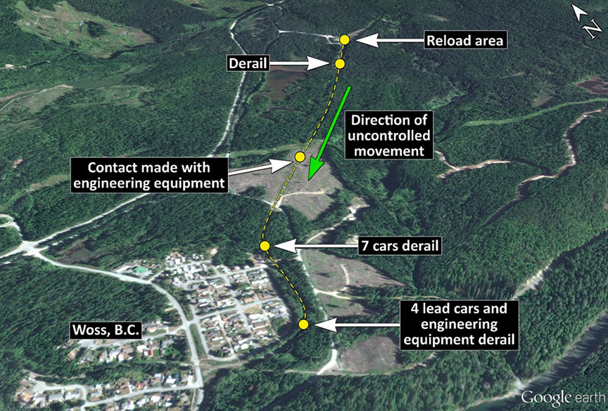
On 20 April 2017, at about 0830 Pacific Daylight Time, a cut of 11 cars loaded with logs rolled uncontrolled out of the Woss Reload Centre operated by Western Forest Products Inc. near Woss, British Columbia. The uncontrolled cars rolled over a derail, re-railed at a switch, continued onto the “H” line track, down the grade, and struck occupied on-track engineering work equipment. The 11 cars and 2 engineering work equipment vehicles derailed. Three engineering employees were fatally injured, and 2 were seriously injured.
Although this railway company falls under provincial jurisdiction, the TSB conducted the investigation at the request of the British Columbia Ministry of Transportation and Infrastructure in accordance with a memorandum of understanding.
1.0 Factual information
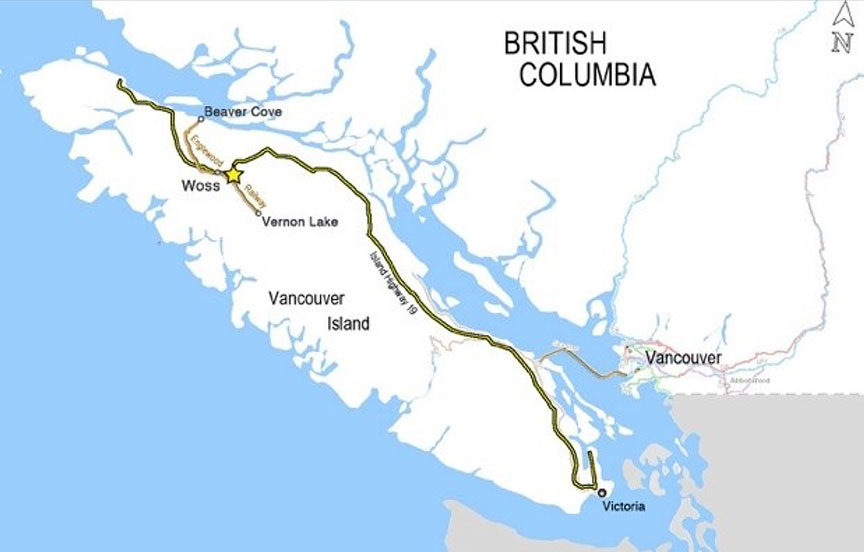
The Englewood Railway, owned and operated by Western Forest Products Inc. (WFP), is located on the north part of Vancouver Island, British Columbia. Englewood Railway is classified as an industrial railway.Footnote 1 It falls under provincial jurisdiction and was certified to operate in British Columbia.
The railway consists of a 90 km (56-mile) mainline—the Nimpkish Subdivision (the subdivision)—and a number of spur lines connecting 4 log reload centres. The subdivision starts at the tidewater timber sorting and rafting facility at Beaver Cove, British Columbia (Mile 1.0), continues through Woss, British Columbia (Mile 37.7), and terminates at Vernon Lake, British Columbia (Mile 56.4) (Figure 1).
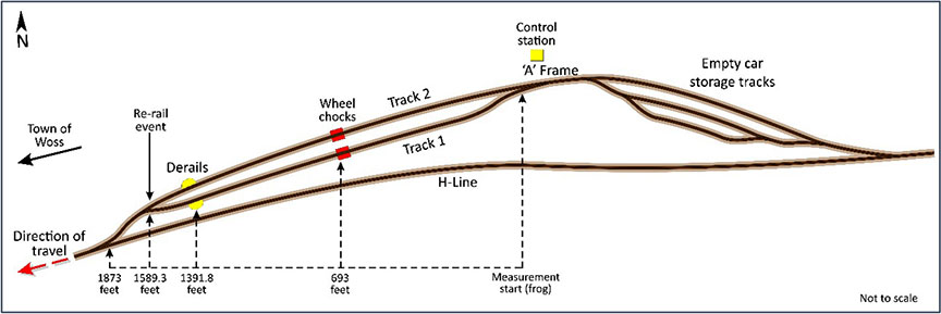
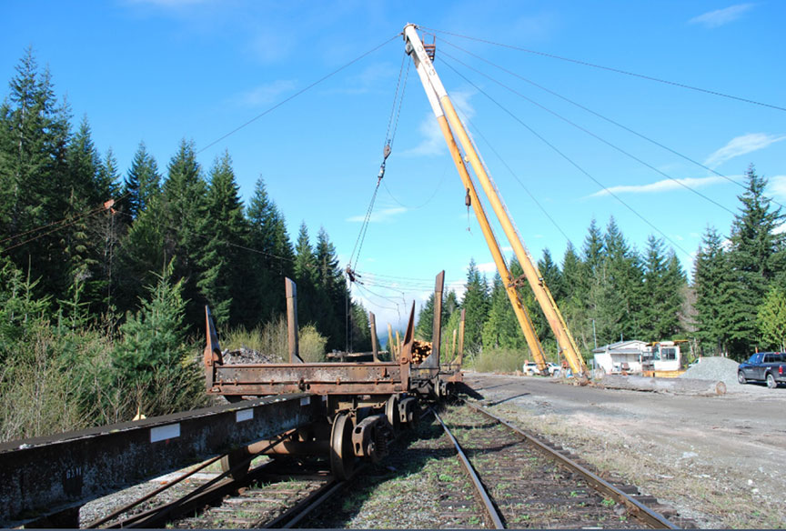
The Woss Reload Centre (the reload) is located about 2.5 km east of the town of Woss. The reload is built on a slope descending from east to west (Figure 2). The rail cars are handled using a gravity and winch cable control system while they are loaded and switched at the reload.
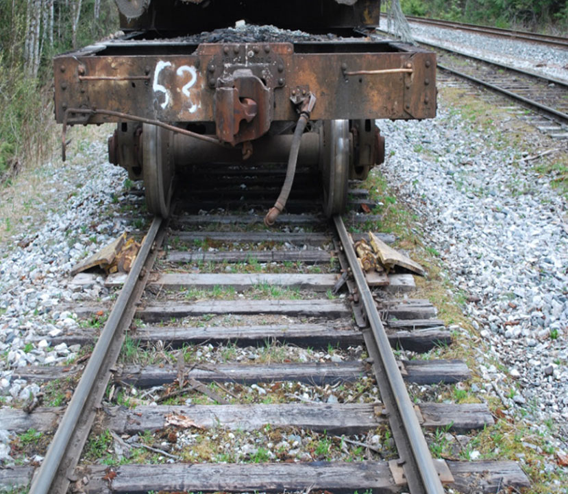
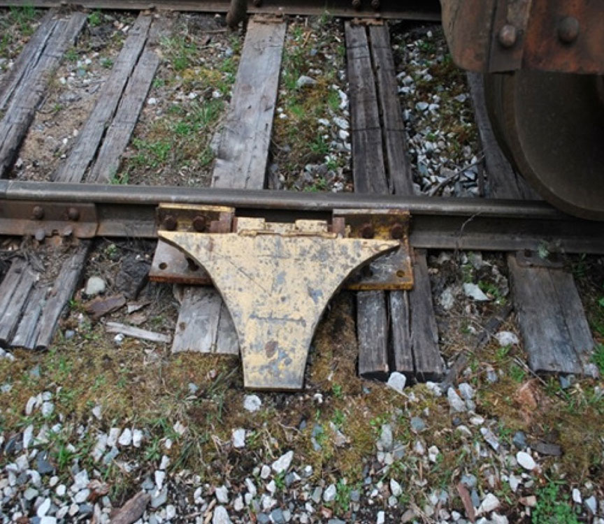
Each car in log service has a hitch welded to the side of the car (Figure 3). A clevis and pin arrangement is used to attach the winch cable to the hitch. Once cars are positioned for loading, wheel chocks (Figure 4 and Figure 5) and hand brakes are used to secure the cars at the top end of Track 1 and Track 2, near the A-frame.Footnote 2 A reload operator controls the winch from the control station. A head loader handles the cable attachment and detachment, switching, and car securement duties.

During loading operations, the head loader and the reload operator communicate using portable 2-way radios. Once the cars are loaded and coupled together, a pull testFootnote 3 is performed to verify that the couplings are secure. After the couplings are confirmed, the wheel chocks are removed, the hand brakes are released, and the cars are lowered to the west end of the loading tracks. Loaded cars are secured and stored at the west end of the loading tracks until there are sufficient cars to operate a train to Beaver Cove.
DerailsFootnote 4 installed at the west end of Track 1 and Track 2 at the reload are intended to prevent uncontrolled cars from exiting the reload. The grade on Track 1 and on Track 2in the Woss Reload (between the A-frame and the derails) varies between 0.3% and 2.2%.
A non–main track spur line, referred to as the "H" line, connects the reload to the Nimpkish Subdivision at the town of Woss. From the reload, the "H" line descends steeply and continuously over a distance of 2.5 km (1.5 miles). The controlling grade on the "H" line is 3%.Footnote 5 Before the "H" line joins the mainline, there are 2 curves: the first curve is an 11° left‑hand curve with a superelevation of 1½ inches, and the second curve is a 14° right‑hand curve with a superelevation of 1¾ inches.
1.1 The accident
On 20 April 2017, at approximately 0700,Footnote 6 a 5‑person engineering employee crew was changing out ties at the west end of Track 2 within the reload. Because loading activities were under way, the engineering employees relocated to replace a defective rail on the "H" line spur track, about 0.9 km (2945 feet)Footnote 7 downhill from the reload.
Shortly after 0810, the reload crew finished loading 5 cars. These cars were then lowered onto 7 loaded cars that were already positioned in Track 2. To lower the cars down Track 2, the cable was attached to the hitch on the downhill car. When the head loader noticed that engineering work was still required on Track 2, it was decided to lower any additional loaded cars down Track 1. The cars already positioned in Track 2were secured with hand brakes.
The winch cable was then connected to loaded car 1043. This car was pulled out of Track 2 and lowered down Track 1 to be coupled to 11 loaded cars weighing about 756.4 tons. These cars had been placed in Track 1 the day before and had been secured with 4 hand brakes and wheel chocks. The crew intended to lower all 12 cars further west in Track 1 to make room for additional cars they would load throughout the shift. All of the loaded cars were scheduled to be taken to Beaver Cove for unloading later that day.
The head loader was positioned beside car 733 (i.e., the east end car of the 11 loaded cars in Track 1). From this position, the head loader provided radio instructions to the reload operator concerning the progress of car 1043 toward car 733.
After the couplers of car 1043 and car 733 came together, a pull test was performed to confirm that the couplers had made a positive coupling. To conduct the pull test, the reload operator reversed the winch and applied tension to the cable to pull the cars eastward. The coupling did not pull apart, and the pull test was deemed successful.
The crew's next switching action was to spot the cut of cars further west on Track 1. To initiate this action, the head loader released the 4 hand brakes and removed the wheel chocks. Using the winch cable, the reload operator pulled the cut of cars eastward to initiate movement. After the tension on the winch cable was released, the cut of cars began rolling westward. The head loader informed the reload operator by radio of the progress of the cut of cars as it rolled toward the west end of Track 1.
Nearing the location where the cut of cars was to be spotted, the head loader observed a ribbon on a rail identifying a location for future track maintenance. The head loader told the reload operator to bring the movement to a stop. The head loader noticed that there was more room and then told the reload operator to let the cut of cars roll down another car length to the spot. The reload operator released the winch cable brake, allowing the cut of cars to roll slowly westward. When the lead car neared the spot, the head loader told the reload operator to stop. The reload operator replied that the movement was stopped. However, the head loader noted that the cars adjacent to him were still rolling westward. The head loader looked eastward up Track 1 where car 1043 had stopped with the cable attached. The coupling between car 1043 and car 733 had released, allowing the 11 loaded log cars to roll uncontrolled westward down Track 1. The coupler knuckle on car 1043 was in the open position.
At about 0832 at the west end of Track 1, the lead car (car 1050) of the uncontrolled movement encountered the derail, which was lined and secured in the derailing position. When the lead truck struck the derail, both wheelsets were diverted off the running surface of the rails. The impact of the wheelsets damaged the derail and rendered it inoperable. No additional wheelsets derailed as the uncontrolled cars travelled over the derail location. The impact of the second truck and following trucks likely further damaged the derail.
About 200 feet further downhill, the lead car reached the switch where Track 1 and Track 2 converge. At this location, the derailed wheelsets struck and broke the rail on Track 2next to the frog of the Track 1/Track 2turnout, and then travelled further and struck the heel blocksFootnote 8 of the switch, which re-railed the wheelsets (i.e., they climbed back onto the running surface of the rails). With all wheels back on the rails, the uncontrolled cut of cars continued downhill on the "H" line track.
Realizing that the cars had not stopped at the derail, the head loader radioed the reload operator and said that the 11 cars were travelling downhill uncontrolled. Using the Woss radio channel, the reload operator tried twice to contact the rail traffic controller (RTC) to report the uncontrolled movement. Unable to contact the RTC on that channel, the reload operator switched to the railway channel and was then successful. The reload operator informed the RTC that an uncontrolled cut of cars had left the reload and was travelling downhill on the "H" line track. The RTC then broadcasted a radio message to everyone in the vicinity of the reload, stating that a cut of cars was rolling uncontrolled and to get out of the way.
At about 0835, the uncontrolled cut of cars reached the engineering employees' equipment and the 5 workers on the "H" line track. Four of the workers were in the on-track engineering vehicle (the speeder), and the 5th worker was in a railway wheel–equipped backhoe. The cut of cars collided with the work equipment, propelling the equipment downhill. About 1730 feet further, within an 11° left-hand curve, the 7 cars at the east end (i.e., the tail end) of the uncontrolled cut of cars separated and derailed. The remaining 4 cars and the 2 engineering work vehicles continued an additional 881 feet, where they derailed within a 14° right-hand curve. Three of the engineering employees were fatally injured, and 2 engineering employees were seriously injured.
The following timeline of events was constructed based on information collected from multiple sources during the investigation. There was limited recorded information available that would have permitted accurate time stamping of these events. Therefore, all times expressed are approximate (Table 1).
| Time (approx.) | Events |
|---|---|
| 0630 |
|
| 0700 to 0745 |
|
| 0645 to 0820 |
|
| 0820 to 0825 |
|
| 0826 to 0830 |
|
| 0830 to 0831 |
|
| 0832 |
|
| 0832 |
|
| 0833 |
|
| 0833 |
|
| 0834 |
|
| 0835 |
|
| 0835:07 |
|
| 0835:50 |
|
| 0836:02 |
|
1.2 Site examination
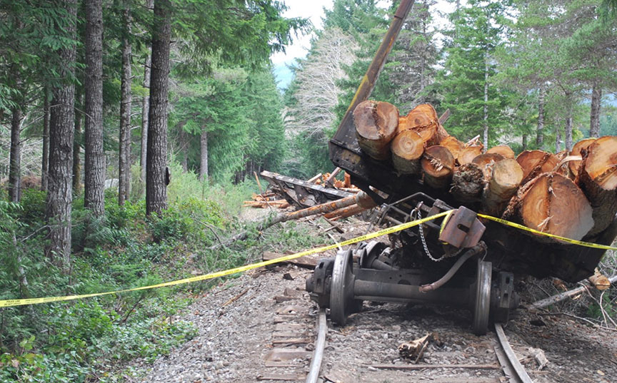
The occurrence site was examined, including the 2 locations where the rail cars derailed (Figure 6 and Figure 7).

At the first derailment location, the 7 derailed cars were positioned in various orientations through the curve, predominantly leaning or rolled to the high side (the right-hand side) of the curve (Figure 8). Damage to the vertical braces on the north side of some of the cars (e.g., car 738) matched gouge marks in the ballast to the north of the track. There were no wheel flange marks between the rails at the point of derailment and no wheel flange marks on the rails or ties approaching the curve. The cars were tipped over with their loads of logs strewn throughout the curve and on top of some of the derailed cars. The 7th car (car 738) had derailed on the exit spiral of the curve, just north of the A Browne crossing.
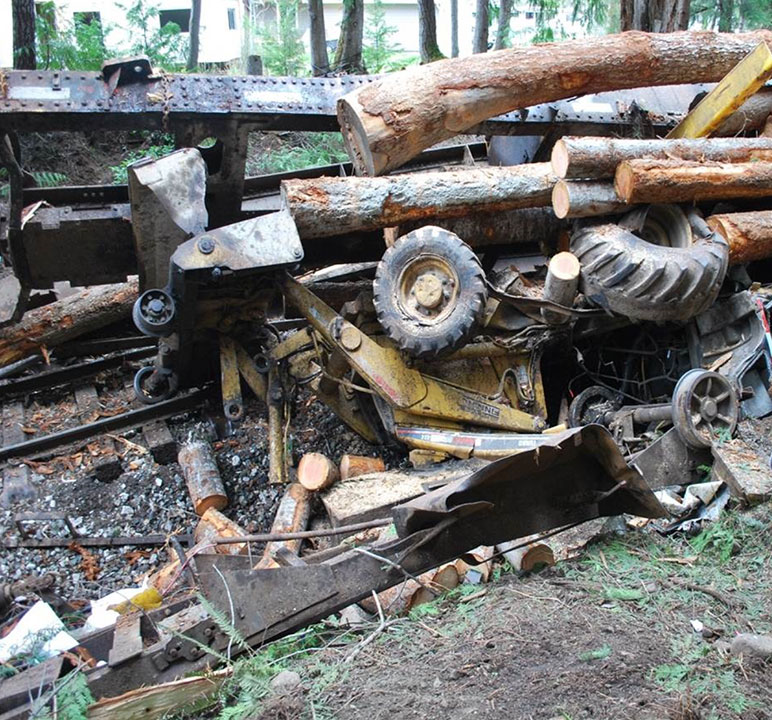
At the second derailment location, the remaining 4 cars, the speeder and the backhoe had derailed to the high side, in the body of the 14° right-hand curve. At this location, the track had shifted to the inside of the curve, which is consistent with cars tipping to the high side. The cars had lost their loads of logs, with some logs burying the backhoe and the speeder (Figure 9). The weight of the logs and the impact forces during the collision and derailment severely damaged the speeder and the backhoe (Figure 10).

1.3 Regulatory oversight of provincial railways in British Columbia
In British Columbia, provincial railways are regulated by the British Columbia Ministry of Transportation and Infrastructure and require 3 approvals:
- a certificate issued by the Minister under the authority of the Railway Act;
- a certificate issued by the Minister under the authority of the Railway Safety Act; indicating approval of the railway's safety management system (SMS) plan; and
- an operating permit issued by the Registrar of Railway Safety under the authority of the Railway Safety Act.
Regulatory oversight is conducted by the British Columbia Safety Authority (BCSA)Footnote 9 for railways that operate solely within British Columbia and that have a certificate issued by the BC Ministry of Transportation and Infrastructure.
Provincial railways are subject to the Railway Safety Adopted Provisions Regulation, which adopted federal railway safety regulations, rules, and standards and revisions thereto.Footnote 10 The Railway Safety Program regulates 5 classes of railway: common carriers, heritage, commuter, industrial, and industrial sidings and spurs. For ease of use by industrial railways, BCSA reproduces the applicable federal safety regulations, rules, and standards as guidelines with slight modifications to reflect the terminology specified in the Railway Safety Adopted Provisions Regulation.
BCSA aims to update these guidelines as the federal regulations, rules, and standards change. In this investigation, it was noted that not all of the referenced federal regulations, rules, and standards had been updated. However, the specific sections referenced in this investigation were unchanged in the updated versions.
1.4 The loading crew
The loading crew at the Woss Reload Centre consisted of 2 employees: the reload operator and the head loader. Both crew members were part of the Yard and Loading Division of WFP. The reload operator had worked for WFP and another forest products company in various positions for 38 years, and had been a reload operator on and off for about 20 years. The head loader had worked for WFP for 4 years and had been a head loader for about 2 years.
This crew normally worked the shift from 0630 to 1600, 9.5 hours a day. The crew schedule consisted of 6 days of work, followed by 3 days off. The 6 work days were often split between the Woss Reload Centre and the Nimpkish Reload Centre.
On the morning of the occurrence, both crew members had started work at about 0630. The crew had originally been scheduled to work at the Nimpkish Reload Centre. However, the Nimpkish Reload Centre had a faulty weigh scale, so the crew was reassigned to the Woss Reload Centre. Neither of the crew members had experienced any recent problems with sleeping, and fatigue was not considered an issue on the day of the occurrence.
1.5 Nimpkish Subdivision and "H" line track
Movements on the Nimpkish Subdivision are conducted in accordance with the BCSA Guidelines pursuant to the Transport Canada–approved Canadian Rail Operating Rules (CROR) and controlled by an RTC located at Woss. The subdivision operates under the occupancy control system (OCS).Footnote 11
The "H" line track is a spur line that connects the Woss Reload Centre to the Nimpkish Subdivision at Mile 37.7. This track is considered non-main trackFootnote 12 as per CROR Rule 105 – Operation on Non-Main Track. The "H" line track consisted mostly of 85-pound rail, with a small portion of track within the occurrence site being 80-pound rail. The rail had been manufactured from 1901 to 1944, and the installation date of the rail was around 1950.
1.6 Woss Reload Centre
The Woss Reload Centre facilitated the offloading of logs from trucks onto rail cars. Once the logs are transferred to rail cars, they are transported by rail to the timber sorting and rafting facility at Beaver Cove. In 2015 and 2016, 5347 and 5621 rail cars, respectively, were loaded and transported to the Beaver Cove facility from the Woss Reload Centre.
The rail within the Woss Reload Centre had been manufactured from 1906 to 1958, and was mainly 85-pound rail.
At this facility, a winch cable operated by the reload operator from a control station (Figure 11) was used to move (switch) the rail cars. The logs on the trucks were unloaded onto rail cars using an A-frame arrangement under the guidance of the head loader (Figure 12). The head loader directed the movement of the rail cars. With the assistance of the reload operator, the head loader directed the pull tests to ensure that the rail cars were coupled together securely. The head loader was also responsible for attaching the winch cable to or removing it from the rail cars.

1.7 Derails
Derails are common track appliances designed to derail and stop the movement of uncontrolled rail cars in order to protect a specific location from the incursion of uncontrolled or unauthorized movements.
Most derails are designed to guide the flange of a car wheel up and over the rail head and divert it laterally to drop the wheel clear of the rail on the field side (outside) of the rail. Movement of the derailed cars then slows and stops when the wheels lodge in the tie cribbing and the ballast. While it is not common for derailed wheels to re-rail, it is possible. However, it is very rare for rolling stock derailed by a derail to re-rail itself.Footnote 13 In many of these situations, the derailed wheels encountered a crossing or a track switch component, such as a frog or a heel block, that guided the wheels back onto the running surface of the rails.
At the Woss Reload Centre, all of the ties, including the ties on which the derails were mounted, were untreated yellow softwood cypress ties.Footnote 14 Cypress is light, hard, strong, and decay-resistant, but not as strong as hardwoods such as maple and oak. Cypress ties were locally sourced, readily available and considered more environmentally friendly than treated ties.
The derails installed on the Englewood Railway were Model HB sliding derails with a wheel crowder (Figure 13) manufactured by Western-Cullen-Hayes, Inc. With a wheel crowder installed, the flange of one wheel is "crowded" or pushed toward the derail block on the opposite side. The flange of the other wheel will strike and climb the derail block, move over the rail head, and drop onto the ties and ballast. This type of derail can be designed and configured to derail rolling stock to the right or to the left, depending on the specific needs at each particular installation.
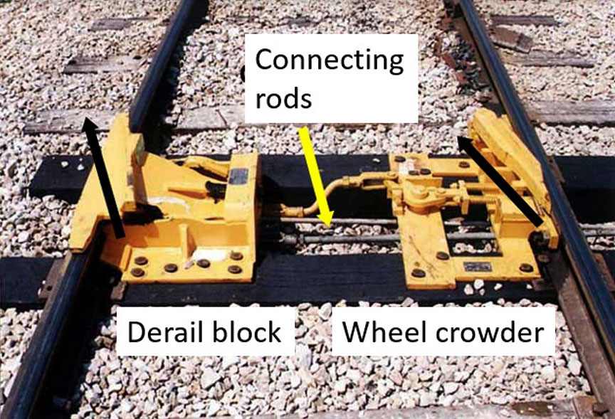
The subject derail was configured to derail rolling stock to the right (in the direction of travel). The wheel crowder was on the left side, and the derail block was on the right side (Figure 14).
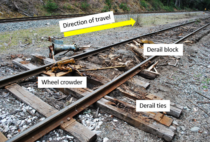
During site examination, the following observations were made:
- At the derail protecting Track 1 at the Woss Reload Centre, the derail block had been completely removed.
- The switch stand was pulled over and the ties were displaced to the north as the sliding derail was removed, allowing the crowder to disengage.
- Spikes were ripped out and the derail ties were destroyed. The derail ties had been displaced laterally by about 28 inches.
- The ties were severely degraded. Interior rot in the centre of these ties was more visible following the removal of the derail block.
- The derail block had 12 holes in the flat tie flanges of the guide box that could be filled with spikes. Only 8 derail spikes were recovered at the site.
- The spikes used were straight spikes, which is acceptable according to the manufacturer's installation instructions.
- The ballast was fouled with fine grain particulate matter inhibiting proper support and drainage.
1.7.1 Rules relating to track appliances
WFP's Englewood Railway follows the Rules Respecting Track Safety Guidelines for British Columbia Provincial Industrial Railways when performing track and derail inspections. These rules are based on the TC-approved Rules Respecting Track Safety, also known as the Track Safety Rules (TSR).
The Rules Respecting Track Safety Guidelines for British Columbia Provincial Industrial Railways state the following with regard to derails:
II. Derails
Each derail must be clearly visible. When in a locked position a derail must be free of any lost motion which would allow it to be operated without removing the lock.
Derails must be installed when there is any possibility of equipment that has been left standing on tracks other than main tracks or sidings being moved by gravity so as to obstruct a main track or siding.Footnote 15
1.7.2 Additional requirements for derails established by other railways
In addition to the TSR, the Canadian National Railway Company (CN) and the Canadian Pacific Railway (CP) have other requirements relating to the installation and inspection of derails. These requirements are set out in the CN Engineering Track Standards and the CP Red Book of Track and Structures Requirements. These higher company standards are not directly applicable to WFP's railway, which is a provincially regulated industrial railway.
With regard to inspecting derails, the CN Engineering Track Standards state the following:
39. Derails must be inspected by the Track Supervisor, Assistant Track Supervisor, Track Inspector or other qualified inspector monthly noting:
- Proper size, type and fit. See T.S. 3.2- DERAILS.
- Derail is in working conditions [sic] or shows signs of damage from impact.
- Ties under derails are sound, fasteners intact and the tie fully supports the derail.
- Lock is present and applied to the derail.
- Derail is painted yellow and clearly visible.
- Derail signs and targets, where required, are in place, retro-reflective and visible.Footnote 16
The guidance documents produced by CNFootnote 17 and CPFootnote 18 indicate that hinge and sliding (such as used in this occurrence) derails may be installed where the speed of the equipment to be derailed will not exceed 15 mph. WFP's use of a siding derail with a stand and a wheel crowder met the design standards used by CP and CN for speeds between 9 and 15 mph.
CN and CP engineering standards indicate that hinge derails and sliding derails are to be installed on fully supported hardwood ties, and that these derails are to be fastened with screw spikes with all holes in the horizontal guide box filled.
1.7.3 Guidance provided by the derail manufacturer
Guidance provided by Western-Cullen-Hayes, Inc., the manufacturer of the derail, in Derails: Installation, Inspection, Maintenance includes the following:
3.1 Site Requirements
[…]
1. The track must be in good condition at the two ties where the derail is to be installed. The ties should be sound and firmly tamped up, are [sic] at right angles to the rail and must hold the rail firmly to the gauge.
[…]
4.1 Locating the Derail
The distance the derail is to be placed from the point requiring protection should be determined by the probable distance the car will travel after being derailed. This depends on length of track, the grade and the condition of the soil.Footnote 19
Section 4.5, Making The Derail A Fixed Part of The Track, of the guidance states that all 6 openings in the horizontal tie flanges of the guide box should be filled with spikes/screws so that the derail may be firmly affixed to the ties. Ties should be spaced so that vertical guide box flanges bear against the sides of the ties.
Section 11.1, Inspection Data Required, of the same guidance calls for the inspection of 18 items including the derails ties ensuring they are sound and firmly tamped, all holes in the horizontal guide box are filled with spikes and the proper model and size of derail is installed in accordance with manufacturer specifications.
1.8 Track and derail inspections
When performing track and derail inspections, Englewood Railway followed the requirements of the TSR. The track in the area of the occurrence was being inspected by hi-rail vehicle at least once a week (per Class 2 standards). During the inspections conducted between 18 January and 18 April 2017, no defects were noted in the vicinity of the occurrence.
Although the derails were observed during the routine track inspections, no specific derail inspection form or protocol was used to document this activity. The railway had no records of the installation or of any inspections or maintenance of its derails.
From a provincial regulatory perspective, the derail was considered compliant with the adopted TSR that govern track infrastructure as well as inspection requirements.
1.9 Track inspector training
With respect to the training of track inspectors, the Rules Respecting Track Safety Guidelines for British Columbia Provincial Industrial Railways state the following:
7.1 Each railway company to which these Guidelines apply shall qualify and certify Track Supervisors and Track Inspectors to inspect track for defects or supervise restoration or renewal of track under traffic conditions. Each person certified shall have:
- At least
- 1 year of experience in railway track inspection or maintenance and training from a course in track inspection and maintenance; or
- A combination of experience in track inspection or maintenance and training from a course in track inspection or from a college level educational program related to track inspection.
- Demonstrated to the railway company that he or she:
- knows and understands the requirement of the TSR;
- Can detect deviations from those requirements; and
- Can prescribe appropriate remedial action to correct or safely compensate for those deviations; and
- A railway company shall maintain a record of all employees who have been certified. Recertification must be completed at intervals not exceeding three years. Records shall be made available, on request, to a BCSA Rail Safety Inspector.Footnote 20
Englewood Railway employees were trained and qualified in regulatory operating rules and track inspection through training programs that had been developed and delivered by an independent railway services contractor and consulting company. A review of the training records revealed that 6 track inspectors had been qualified on 20 June 2014. These track inspectors were due for recertification on 20 June 2017.
1.10 Previous derailments on the Englewood Railway
From 2007 to 2015, there were 12 derailmentsFootnote 21 on the Englewood Railway, including the derailment of 3 empty log cars in a 22-car uncontrolled movement over the Track 2 derail at the Vernon Reload Centre on 03 December 2007. In the Vernon Reload occurrence, the cars had been set in motion when a knob attachment on the winch cable broke, allowing the 22 cars to roll uncontrolled down the grade. The movement stopped when 3 of the uncontrolled cars travelled over the derail near the end of the track and derailed as intended.
1.11 British Columbia Safety Authority Railway Safety Program
BCSA conducts annual audits on its provincial railways to assess railway safety. The audit work plan is generally determined by the findings relating to non-compliances identified the previous year during assessments, audits, and accident/incident investigations.
BCSA's State of Safety Report 2016 highlighted that there had been a continuing focus on employee training and proficiency testing. The report also highlighted the following trends over the 5-year period (2012 to 2016):
- An increase in the number of operating provincial railways in British Columbia from 80 to 149
- 131 of 149 operating railways in 2016 were industrial
- An increase in the number of reported railway incidents from 86 to 134
- An increase in the number of reported railway injuries from 6 to 22,Footnote 22 including 4 fatalitiesFootnote 23
1.11.1 Safety management audits of Englewood Railway
BCSA conducted annual safety management audits of Englewood Railway.
Following the 2012 audit, BCSA issued a letter of compliance indicating that the railway did not have a formal process to document its annual SMS review/audit.
In 2013, BCSA conducted a more detailed audit of Englewood Railway. The 2013 audit assessed the railway's compliance with the rules, regulations and SMS requirements as being "effective, except as noted." This assessment rating is used when the audit or review determines that the overall controls are effective, but detailed comments for improvement are included. In this audit, 26 risk findings were identified. Englewood Railway developed corrective action plans to address the following issues:
- The railway could not demonstrate that its operating personnel were qualified for their positions (i.e., track inspectors were not TSR-qualified).
- Track inspections were not being conducted at the required frequency.
- Walking inspections were not being documented.
- Track geometry or rail flaw detection had not been conducted as required.
- The railway had no way of measuring or tracking non-urgent defects.
- Operating staff were not consistently following CROR rules, including calling signals, OCS clearance procedures, and radio communication practices.
- The railway did not have General Operating Instructions (GOIs).
The actions taken by Englewood Railway are listed in Appendix B.
The BCSA's May 2014 audit determined that 21 of the 26 findings (81%) had been adequately addressed. However, the unresolved risk findings included
- ensuring that track supervisors and inspectors were all TSR-qualifiedFootnote 24; and
- ensuring that walking inspections were being performed and documented.Footnote 25
In 2015, the BCSA audit noted that weekly track inspections were not always being performed.Footnote 26 The on-site audit coincided with 1 of the 2 derailments reported by Englewood Railway that year.
In 2016, the BCSA audit noted that annual detailed turnout inspections were not conducted. It was also noted that many of the mainline turnouts had ballast that was in poor condition, and that Englewood Railway had no records to confirm that the minimum number of walking track inspections was being performed. The audit assessed the railway's SMS as "effective, except as noted." The audit identified 4 risk findings, as follows:
- Not performing detailed annual turnout inspections as per rules respecting track safety Part II Subpart F, 3.4 (a) (b)Footnote 27
- Poor crosstie and ballast conditions at numerous turnout locations between Steel Creek crossing and Beaver Cove
- Unable to confirm performance of required walking track inspections as per the rules respecting track safetyFootnote 28
- Rail defects are not being managed as per the remedial action table found in the rules respecting track safety Part II Subpart D section (iii)
1.12 Coupler information
Couplers are located at both ends of a rail car to allow the rail car to be connected to other cars. When 2 rail cars are coupled together, the coupler knuckle is designed to transition from an open position to a closed or locked position.
When the coupler is closing, the knuckle rotates in a horizontal plane about the knuckle pin, such that the nose of the knuckle engages with the adjoining coupler and its tail retracts into the coupler body. Once fully retracted, the knuckle tail is restrained by the lock. The lock then drops down between the knuckle tail and the coupler body and prevents the knuckle from opening.
Coupler knuckles are typically opened manually using an uncoupling lever. When the knuckle is opened, as the uncoupling lever is rotated, the lock-lift assembly moves vertically and, in turn, lifts the lock and frees the knuckle tail. As the uncoupling lever rotates further, it forces the leg of the lock to engage the knuckle thrower, opening the knuckle.
To prevent the coupler from being released unintentionally, the lock-lift assembly features an anti-creep design that prevents upward vertical movement of the lock unless the lock-lift assembly is activated by the uncoupling lever.
A coupler assembly is considered an "on-condition" item. This means that the Association of American Railroads (AAR) does not specifically require the inspection of coupler assemblies on a scheduled basis.
There are no field inspection gauges for the locking block, nor is there a finite life for this component.
Part II, section 15, Couplers and Drawbars, of the TC-approved Railway Freight Car Inspection and Safety Rules states (in part):
15.1 A railway company shall not place or continue a car in service if: […]
- the car has a coupler with an inoperative lock-lift or a coupler assembly that does not have anti-creep protection to prevent unintentional unlocking of the coupler lock;
- the coupler lock is missing, inoperative, bent, cracked or broken […].
There is currently no inspection mechanism in the rail industry to ensure that locking blocks are in serviceable condition.
If the coupling process does not generate sufficient movement to allow the coupling to be verified, or if the locks are not heard to drop into place, the general industry practice is to test the coupling of the cars by performing a pull test. An employee is positioned at the coupling as an observer and instructs the locomotive engineer to move in the direction required to apply tension to the coupling. If the coupled cars are observed to move in unison and there is visible tension on the coupling, the coupling is considered successful.
At Englewood Railway, a gravity and winch cable control system, rather than a locomotive, was being used to couple and move the cars. In this occurrence, when the subject cars were coupled, tension was applied to the cable to test the coupling. The test indicated that a successful coupling had occurred.
1.13 Laboratory examination of the coupler
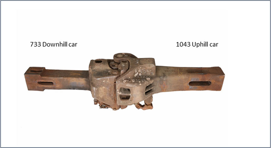
The couplers from the 2 subject cars (car 1043 and car 733) were sent to the TSB Engineering Laboratory for a detailed examination (Figure 15). The primary focus of the examination was to determine why the coupler knuckle of car 1043 inadvertently released after a pull test had been performed and deemed successful.
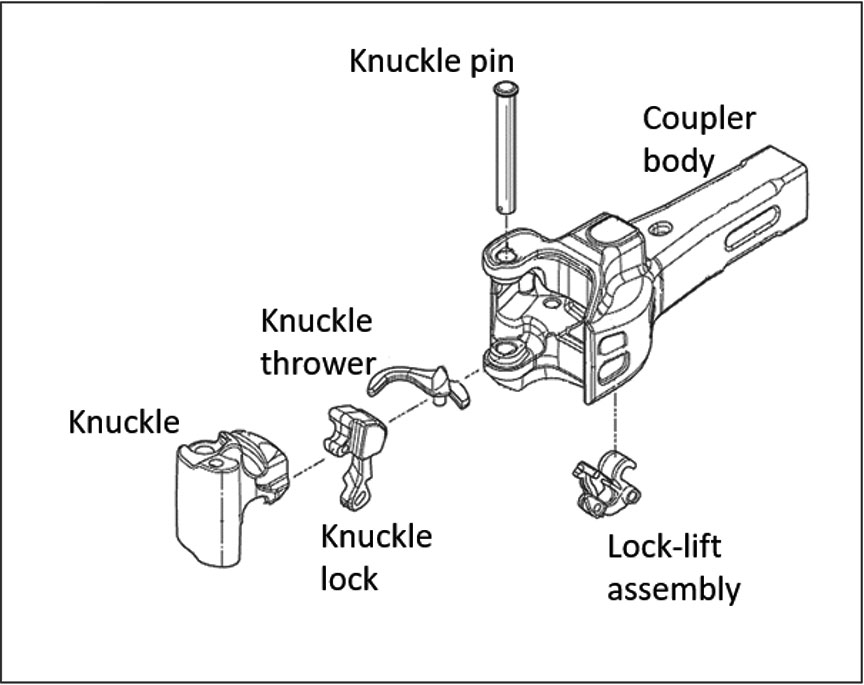
The coupler from car 1043 was a bottom-operated, standard Type E coupler. It consisted of the coupler body, the knuckle, the knuckle lock, the knuckle thrower, the lock-lift assembly, and the knuckle pin (Figure 16). The coupler was manufactured in October 1981.
There were no markings stamped into the horn on the coupler body; this indicated that it had not been reconditioned. There was no cracking, no deformation, and no excessive wear present on the exterior of the coupler body. The coupler exceeded the minimum requirements for shank length and the dimension between the rear of the key slot and the shank butt.
The coupler body, the knuckle, and the lock were manufactured from grade C steel. Although grade C steel coupler bodies are permitted in interchange service, grade E steel locks must be used to meet the correct repair requirements for all couplers when a lock is replaced.Footnote 29 In comparison to grade C steel, grade E steel has increased tensile strength and hardness.
1.13.1 Examination of the coupler and knuckle
As part of the laboratory examination, the coupler and its knuckle were inspected using gauges 25623-1 and 44057, as per the AAR guidelines. The contour of the knuckle and its fit in the coupler body were determined to be acceptable.Footnote 30 However, there was minor deformation with a fresh (not rusted) appearance present on the top edge of the knuckle tail (Figure 17).
1.13.2 Examination of the coupler lock
The coupler lock was a top-operated lock. It is permissible, but not common, to install a top-operated lock in a bottom-operated coupler. Although intended to be dimensionally identical to bottom-operated locks, top-operated locks are approximately 2.2 pounds lighter than bottom-operated locks because they have a cavity in the lock head for the lock lifter attachment.
Although not evident from an external visual examination of the coupler, weld metal with an aged appearance was present on the lock's knuckle engagement surface, indicating a previous repair. Englewood Railway had no records of having performed any weld repairs on the couplers on car 1043. Repairs can be made on coupler locks with a worn knuckle engagement surface by welding and heat-treating the lock, as long as they are performed according to AAR specifications.Footnote 31 However, the weld repair did not meet the original material requirements.
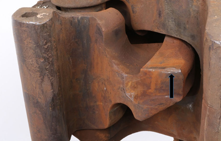
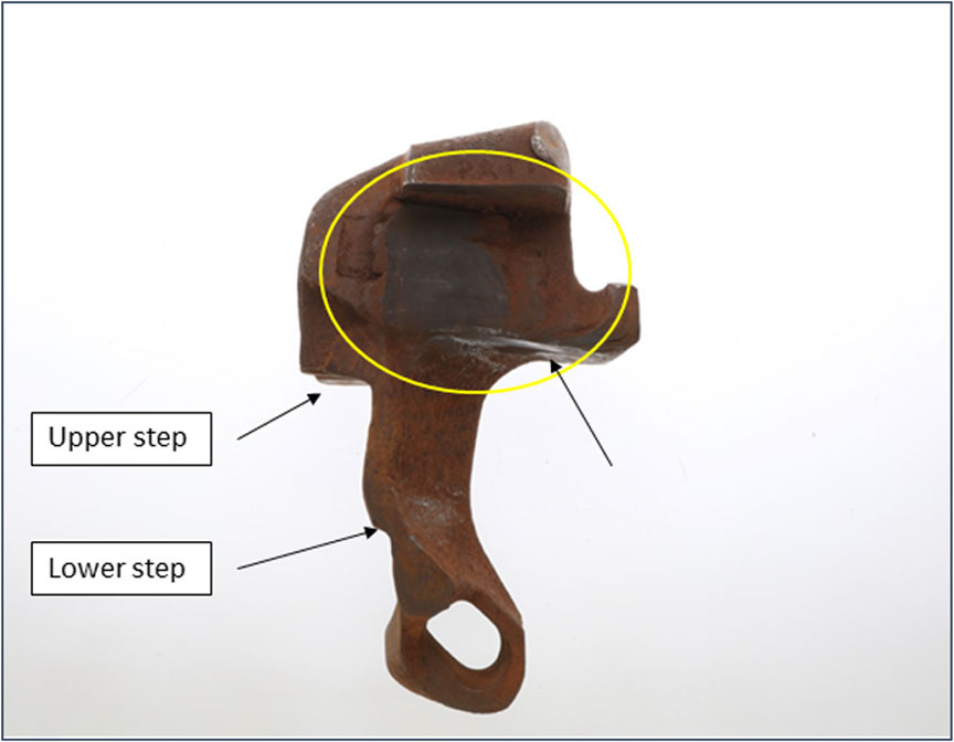
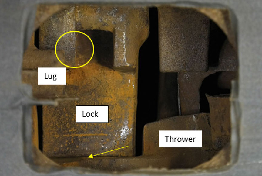
Coupler locks have 2 steps on the back (Figure 187). The larger upper step is where the lock will normally sit on the knuckle thrower when the lock is in the fully dropped and locked position. The smaller lower step is the lock set step used in the knuckle installation procedure where the lock is manually pushed rearward and forced to sit high on the knuckle thrower. This lower step allows the knuckle tail to swing past the lock during installation. The lock set step is not used in normal operation of the coupler.
As part of the laboratory examination, the coupler lock was inspected in accordance with the AAR guidelines for the 2 dimensions governed by go/no-go gauge 49365. The width of the lock was determined to be above the minimum requirement. The depth of the indentation worn in the side of the lock was below the maximum allowable depth due to engagement with the tail of the knuckle. It was determined that the lock was serviceable from a wear perspective.
The subject coupler lock met the dimensional requirements of the inspection gauges. There was no date of manufacture or mention of finite life on the lock. Coupler locks may be reconditioned according to AAR specifications. The coupler lock was likely a replacement and not original to the coupler. There were no records to indicate that Englewood Railway had completed a repair on the coupler lock or had replaced it.
1.13.3 Examination of the coupler lock-lift assembly
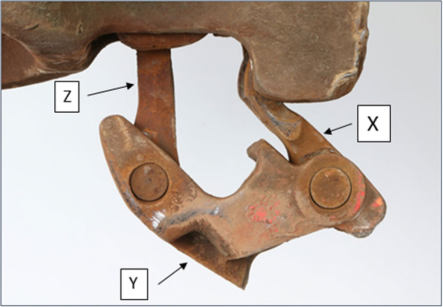
The coupler lock-lift assembly consisted of 3 parts—toggle X, toggle Y, and toggle Z (Figure 19). Toggle X sat on the trunnion at the bottom of the coupler body. Toggle Z engaged with the tail of the coupler lock. Toggle Y, which joined toggle X and toggle Z, provided the attachment point for the uncoupling lever.
The subject lock-lift assembly was examined and showed wear in the toggle joints and rivets. This wear allowed for increased lateral movement of toggle Z, such that the lock could be removed without pulling the lock-lift up through the lock hole.
1.13.4 Examination of the anti-creep protection
The coupler lock is prevented from rising from the locked position by design, using anti-creep protection. The primary anti-creep protection is provided by a cast-in-place lug in the lock hole that engages with toggle Z if toggle Z is not lifted at the same time. Auxiliary anti-creep protection is provided by toggle Y, which engages with the bottom edge of the lock hole if the uncoupling lever and lock-lift assembly parts are thrown forward as a result of sudden deceleration of the car.
As part of the laboratory examination, an anti-creep test was performed on the coupler assembly in accordance with the AAR guidelines.Footnote 32 The assembly passed the anti-creep test, with both the primary and the auxiliary anti-creep protection functioning as intended.
1.13.5 Opening and closing the coupler knuckle
Several times when closing the coupler knuckle, the lock was observed to engage only partially with the knuckle tail (Figure 20 and Figure 21). Deformed areas were present at the top edge of the knuckle tail and on the lower edge of the lock. The deformation on these coupler components was identical.Footnote 33


Several trials involving opening and closing the knuckle were completed with the subject coupler parts and exemplars (typical standard specimens). With the original parts installed, the subject lock did not drop to the locked position every time. Similarly, when the lock-lift assembly or the knuckle thrower was replaced with an exemplar, the subject lock did not drop every time.
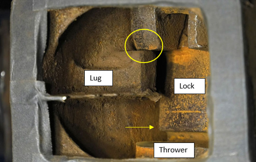
The coupler operation with the original components installed was examined. When the knuckle was opened and the uncoupling lever was released, the subject lock rested on the top of the knuckle tail and on a positioning lug inside the coupler head (Figure 22). In this position, the subject lock was held up inside the coupler head with the lock set step above the top edge of the knuckle thrower. When the knuckle was closed, the lock dropped off the lug and onto the thrower in the lock set position (Figure 23).
With the lock in the set position, partial interference occurred between the tail of the knuckle and the lock at the front. The radius and hardness of the lock contributed to the partial jamming of the knuckle such that the lock was not in the fully dropped and locked position. For the lock to drop off the set step and down to the fully dropped and locked position (Figure 24), it was necessary to open the knuckle a second time and to close it again.

Several trials involving the operation of the coupler were conducted by successively changing out certain components. It was observed that, each time the subject lock was installed, the coupler did not operate as intended.
1.13.6 Dimensional differences in the coupler lock
Comparisons between the subject lock and the replacement locks (used during the laboratory examination) showed several differences.
Manufacturing tolerances combined with wear on the subject lock resulted in dimensional differences in several areas, some of which are key to the proper operation of the coupler. The wear took place on the rear of the coupler-locking block head, which is a non-gaugeable area.
The dimensions of the subject lock allowed it to move rearward such that, when the coupler was opened and released, the lock rested on the top of the knuckle tail and on a positioning lug inside the coupler head. In this position, the lock was held up inside the coupler head with the lock set step above the top edge of the knuckle thrower. This changes the mechanical timing such that, when the knuckle is closed, the lock drops off the lug and onto the thrower in the lock set position, not the fully dropped and locked position.
With the lock in the set position, there was interference between the tail of the knuckle and the lock, but the locking block was not in the fully dropped and locked position.
When the subject lock was replaced with a bottom‑operated lock, it was observed that, in the opened position, the lock rested on the knuckle tail only, as intended.
When the lock was slowly dropped from the fully raised position, it was unable to engage with the lug in the coupler head. This is because the upper step is smaller, the distance from the back of the lock to the edge of the step is greater, and the head of the lock is wider, which prevents it from moving rearward as the subject lock does.
When the lock set step sat on the tail of the knuckle only, and not on the positioning lug, the set step was positioned below the top edge of the knuckle thrower.
When closing, the lock moved upward momentarily due to the geometry of the knuckle tail. However, the lock set step did not rise above the top edge of the knuckle thrower. When fully closed, the lock dropped freely into the locked position.
The examination showed that dimensional differences in the coupler lock prevented the coupler from operating properly. In this occurrence, it is likely that the lock dropped only partially into position, which prevented the knuckle from opening during the successful pull test. Subsequently, when sufficient load was applied, the engaged edges of the lock and the coupler yielded and deformed, causing the lock to rise out of position. This allowed the knuckle to swing open, releasing the cut of cars.
1.14 Radio communications following the uncontrolled movement
The RTC at Englewood Railway had 4 separate radios and was required to monitor 4 separate channels: the railway channel normally used for operations, including emergency communications; the Woss channel; the Nimpkish channel; and the Holbrook–Dyson channel.
On the morning of the occurrence, at about 0650, the engineering employees contacted the RTC to state that they were clear of the "cautionary limits" at Woss and were en route to the "H" line and the Woss Reload Centre.
At approximately 0834, the RTC heard the 2nd attempt by the reload operator to call over the Woss channel. When the RTC answered the call, the reload operator had switched to the railway channel. Once contact was established with the reload operator on the railway channel, the RTC was informed that a cut of cars had rolled uncontrolled out of the Woss Reload Centre onto the "H" line. The RTC immediately made a broadcast over the railway channel about the situation and advised everyone to get clear of the track, but received no reply. The engineering employees who survived the collision did not recall hearing either the reload operator's or the RTC's transmissions over the radio.
Radio communications on the railway were governed by the Western Forest Products (WFP) CROR. Rule 117 states:
The crew of a movement when equipped with radios must carry out an intra-crew test of such radios before leaving their initial terminal, change-off or starting point.Footnote 34
Rule 119 of the WFP CROR states (in part):
When not being used to transmit or receive a communication, receivers must be set to the appropriate standby channel and at a volume which will ensure continuous monitoring. When required to use another channel to perform other duties, at least one radio, when practicable, should be set to the designated standby channel to receive emergency communications.Footnote 35
There were no other standard operating procedures (SOPs) relating to the monitoring or daily checks of radios.
CROR Rule 125, Emergency Communication Procedures, states:
- An employee will transmit the word "EMERGENCY" three times at the beginning of the transmission to indicate the report of;
- an accident involving injury to employees or others;
- a condition which may constitute a hazard to employees or others;
- a condition which may endanger the passage of movements; or
- a derailment which has occurred on, or is fouling, a main track.
- When an emergency communication, which is directed to a specific person or movement, has not been acknowledged, any other employee hearing it will, if practicable, relay the communication by any means available. Other employees must not interfere with such communication.
- An emergency communication has absolute priority over other transmissions.Footnote 36
In this occurrence, the reload operator had decided to inform the RTC of the uncontrolled movement rather than make the emergency radio call over the railway channel. When the emergency situation was broadcasted by the RTC over the railway channel, the transmission did not begin with the word "emergency" 3 times. Emergency procedures, including emergency radio communications, were not practised by the railway.
1.15 Laboratory examination of the radios
Three radios from the engineering employees' equipment were recovered and sent to the TSB Laboratory for detailed examination.
1.15.1 Radio 1: Motorola CDM1250 dash mount
This radio was obtained from the engineering speeder that was transporting 4 of the engineering employees. The radio had the volume button set at the middle position, and had been set to the railway repeaterFootnote 37 channel.
The rear 20-pin connector accessories adapter was damaged. However, this damage would not have affected the radio's ability to receive and transmit.
TSB laboratory tests conducted using the 2 railway channels (railway repeater and railway direct) concluded that the radio receiver operated with the company‑given frequencies. However, the radio failed to transmit due to damaged circuitry, likely sustained during the occurrence.
1.15.2 Radio 2: Motorola HT750 handheld
This radio was obtained from the engineering speeder. The radio had the power/volume button set to the off position, so it was likely not in operation during the occurrence. The channel knob was set to position 2, which was the railway repeater channel.
TSB laboratory tests conducted using the 2 railway channels concluded that the radio receiver operated with the company‑given frequencies and transmitted at the company‑given frequencies within acceptable offset tolerances.
1.15.3 Radio 3: Motorola CM300
This radio was obtained from the backhoe. The radio had the volume button, which also acts as the power on/off button, set to the off position. The radio had been set to the railway repeater channel.
TSB laboratory tests conducted using the 2 railway channels concluded that the radio receiver operated with the company‑given frequencies.
1.16 Line-of-sight study for radio communications
Radio communications on the Englewood Railway were conducted in accordance with the CROR. Because radio communications were not recorded, the communications transmitted and received in this occurrence could not be specifically established and/or confirmed. However, the surviving engineering employees did not recall hearing a warning broadcast before being struck by the uncontrolled movement.
Radio communications can be adversely affected by the local topography and the location of radio antenna towers. Where radio signals cannot be transmitted or received, there is a radio dead spot. To determine if these conditions existed for the engineering employees, a line-of‑sight study was conducted. Based on this study, the local topography and the positioning of the radio antenna towers would not have prevented radio communications with the engineering employees.
1.17 Simulations of the uncontrolled movement
The TSB laboratory conducted a number of simulations of the uncontrolled movement using the Train Energy and Dynamics Simulator. The train model and the track file for the simulation were created using the data from the occurrence cars, the surveyed grades, and the curve data. The investigation could not identify the precise location where the movement became uncontrolled. Therefore, 2 locations were selected for simulation.
1.17.1 Simulation 1
In the 1st simulation (Table 2), the front end of the downhill car (car 1050) was at the wheel chocks, or 698.8 feet east of the derail. The front end of the downhill car (car 1050) was located at the wheel chocks when the pull test was performed.
| Reference point | Point on the track | Distance from reference point (feet) | Time (seconds) | Speed (mph) | Comments |
|---|---|---|---|---|---|
| 1 | Line at frog between Track 1 and Track 2 | 0 | 0 | 0 | Measurement start point |
| 2 | Wheel chocks | 693 | 0 | 0 | |
| 3 | Derail | 1391.8 | 67.11 | 15.16 | One set of trucks derailed |
| 4 | Heel blocks | 1589.3 | 77.31 | 11.07 | The set of trucks re-railed |
| 5 | "H" line switch | 1873 | 92.06 | 15.05 | |
| 6 | Start of debris field | 4818.4 | 166.97 | 42.34 | Point of impact with the engineering equipment |
| 7 | Entrance of left-hand curve | 6161 | 186.37 | 51.8 | |
| 8 | Exit of left-hand curve | 6595 | 191.96 | 54.01 | 7 trailing cars derailed with car 738 derailing past crossing |
| 9 | South end of single car derailed (car 738) | 6820.6 | 194.78 | 55.14 | 7 trailing cars derailed with car 738 derailing past crossing |
| 10 | Entrance of right-hand curve | 7215 | 201.17 | 56.65 | |
| 11 | Location of northernmost derailed car | 7558.5 | 203.68 | 57.85 | 4 cars and engineering equipment derailed |
1.17.2 Simulation 2
In the 2nd simulation (Table 3), the front end of the downhill car (car 1050) was 320 feet east of the derail. The movement was near this position when the call to stop was made 1 car length to the east of the intended spot location. This simulation also determined the minimum distance required for the uncontrolled movement to retain sufficient inertia to re-rail at the heel blocks at the Track 1/Track 2switch.
| Reference point | Point on the track | Distance from reference point (feet) | Time (seconds) | Speed (mph) | Comments |
|---|---|---|---|---|---|
| 1 | Line at frog between Track 1 and Track 2 | 0 | 0 | 0 | Measurement start point |
| 3 | Wheel chocks | 693 | 0 | 0 | |
| 3X | North end of cars (assumed) | 1072 | 0 | 0 | Minimum distance for re-rail event |
| 4 | Derail | 1391.8 | 41.15 | 10.89 | One set of trucks derailed |
| 5 | Switch point past rail break | 1589.3 | 63.61 | 0.61 | The set of trucks re-railed |
| 6 | "H" line switch | 1873 | 100.39 | 10.16 | |
| 7 | Start of oil and debris field | 4818.4 | 186.22 | 40.87 | Point of impact with the engineering equipment |
| 8 | Entrance of left-hand curve | 6161 | 206.20 | 50.63 | |
| 9 | Exit of left-hand curve | 6595 | 211.92 | 52.89 | 7 trailing cars derailed with car 738 derailing past crossing |
| 10 | South end of single car derailed (car 738) | 6820.6 | 214.79 | 54.13 | 7 trailing cars derailed with car 738 derailing past crossing |
| 11 | Entrance of right-hand curve | 7215 | 219.68 | 55.7 | |
| 12 | Location of northernmost derailed car | 7558.5 | 223.85 | 56.81 | 4 cars and engineering equipment derailed |
1.18 Number of derailed wheelsets required to stop the uncontrolled movement
A simulation was conducted to determine the minimum number of derailed wheelsets required to stop the occurrence movement before it reached the heel blocks for the switch (where it re-railed).
Using the wheel chocks as the starting point (698.8 feet from the derails), it was concluded that 4 derailed wheelsets, or all of the wheelsets of the lead car, would have stopped the movement about 47 feet short of the heel blocks.
1.19 Training of reload centre workers
The reload centre workers, who were part of the Yard and Loading Division, received training on topics such as the health and safety policy, safe work procedures relating to personal protective equipment, the right to refuse unsafe work, and emergency preparedness and the response plan.
The workers also received CROR training to a "D" level.Footnote 38 This training was delivered by an in-house trainerFootnote 39 and consisted of 3 hours of classroom training, followed by a comprehension test. The materials used to provide CROR training to the reload workers included CROR Rule 113 – Coupling to Equipment and CROR Rule 125 – Emergency Communication Procedures. The comprehension test assessed the worker's understanding of some of the coupling and emergency communication procedures.
The reload centre workers also received training in a number of "safe work procedures" (SWPs) and SOPs relating to the work performed at the reload centres, including the following:
- Log truck in the landing SWP
- Reloads SWP
- Bucking in the landing SWP
- Chaser SWP
- Cables and lines SWP
- Yard and loading SWP
- Yard and loading SOP
The Reloads SWP contains the following information related to switching trains and moving cars:
Switching Trains
- If necessary to get on or step off a train, be sure of your footing.
- When coupling up cars, avoid injury by not attempting to make last second adjustments to the knuckles.
- When hooking cars up to a string of loaded cars, do not get in between cars.
- Do not work on moving cars.
- Stand clear of moving train.
- Stay clear of spotting line when cars are being moved as the spotting line could whiplash. The spotting line must be used when dropping loaded log cars.
- At Woss Reload, load up Track 2first then walk down the Main Track to set chock.
- At Camp A, load up Track 1 first when possible.
Moving Cars
- Sound the whistle before moving a car.
- Do not attempt to stop runaway cars. Derails are installed at each reload to deal with such emergencies. Signal the runaway using a sustained series of short whistles. Get in the clear and let the d-rail do its job.
- The following communication protocol between Head Loader and Reload Engineer while using spotting line to drop loads down the track:
- The Head Loader calls "half way down" and the operator acknowledges, he clearly understood the transmission.
- The Head Loader then starts calling car lengths when approaching the Derail 8, 4, 2, 1, 0.5, 10' and stop, and if the Engineer fails to hear any of the calls, the Reload Engineer STOPS movement of the cars immediately.
- Stop all lines when a signal is not understood.
- When coupling up cars, throttle back in time to ease empties without throwing slack into the spotting line. Once the cars are hooked up, pull back to ensure all cars are securely coupled up.
- Proper positioning can prevent falls while attempting to apply a hand brake that may inadvertently slip. To avoid falling when applying hand brakes, position feet shoulder width apart and staggered. One hand on the brake handle and the other hand on the dog – braced, ready in case the hand brake slips.Footnote 40
At the Woss Reload Centre, the reload operator sounded a whistle when cars were moved. The SWP required that a "sustained series of short whistles" be sounded when cars ran uncontrolled. In this occurrence, the sustained series of short whistles was not sounded to signal the uncontrolled movement.
With regard to coupling to equipment, CROR Rule 113 states (in part):
(d) When coupling to equipment for any purpose except when humping or flat switching where cars are intentionally let run free, the coupling must be stretched to ensure it is secure.Footnote 41
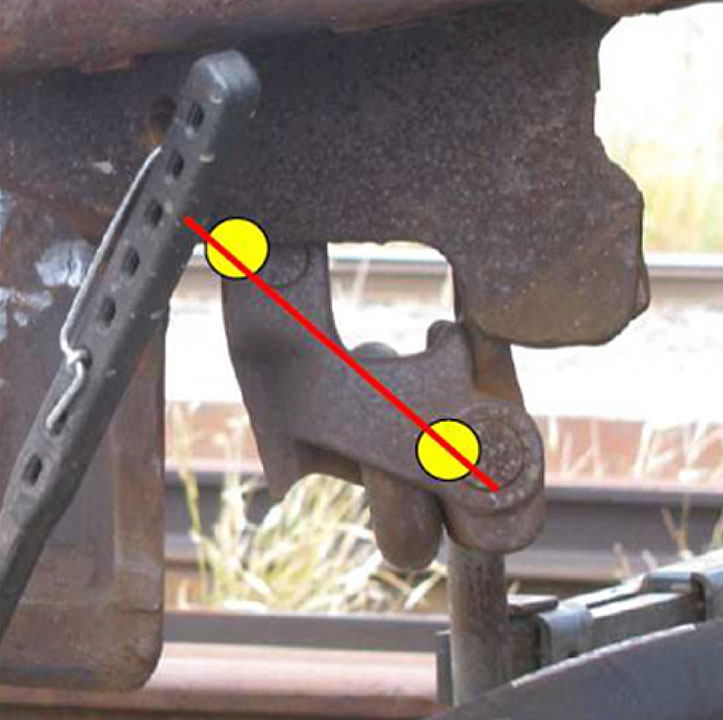
At least one Class I railway instructs operating crew members to visually inspect the coupling to ensure that the bottom-operated lock-lift assembly pivot points are properly aligned. When the coupler locking blocks have dropped properly into place to secure the knuckle, the pivot points will be horizontally aligned (Figure 25 and Figure 26). However, this indicator of a successful coupling was not widely known or circulated in training material throughout the railway industry at the time of the occurrence. Rather, general observation of the bottom lock-lift assembly to verify that the knuckle pin has dropped (i.e., the coupling was successful) has been a long-standing practice throughout the railway industry.

The BCSA Railway Safety Program: Safety Handbook (a support tool for newly certified railways within the province that was not designed to replace the necessary training regime mandated by the regulator) gives the following information about coupling cars:
When coupling cars:
- Ensure that the car being coupled to is properly secured so that the coupling action does not make the car roll away.
- Ensure that you stand clear of the couplers before coupling the trackmobile or other cars.
- Ensure all couplers are aligned and that at least one knuckle is open before coupling to any car.
- Do not adjust drawbars or knuckles, hoses, or angle cocks when cars are about to couple.
- Confirm that any string of cars is fully coupled before moving or leaving, if possible. A slight push or pull should be sufficient.
- Ensure one angle cock is left open after moving cars with coupled air lines.Footnote 42
The safety handbook, which is not a regulatory instrument, did not include information to suggest that the horizontal alignment of the lock-lift assembly pivot points could be used as a means of visually confirming that the locking block has fully dropped to engage the knuckle.
1.19.1 On-the-job training for operating employees at Englewood Railway
At Englewood Railway, the head loader training included on-the-job training in which a trainee was part of the reload centre crew. The trainee began by observing the work being performed, such as
- unloading trucks using the A-frame
- transferring logs from trucks onto rail cars using the A-frame
- the movement of rail cars within the reload centre (empties spotted to A-frame and loads moved downhill for pick-up)
- the use of hand brakes on rail cars
- the use of wheel chocks for the securement of rail cars
- the coupling of rail cars to one another
- the "pull test" to confirm positive connection
- proper radio communication with the reload operator
Experienced employees (acting as trainers) continually instructed, monitored, and assessed trainees on all tasks, including the coupling of rail cars. Trainers provided periodic reports on a trainee's progress to management. In consultation with the trainers, management approved the completion of the training for an individual trainee, as appropriate. Once training was completed, head loaders were considered qualified to perform the job independently.
The head loader in this occurrence had received approximately 6 months of on-the-job training before starting to work independently as a head loader.
The on-the-job training records contained updates on his progress. However, the topics covered during the course of the training were not specifically documented, and there were no documented comprehension tests for each of the required elements.
1.19.1.1 Training specific to the visual verification of successful coupling
For the type of coupler in this occurrence (bottom-operated), a visual confirmation can be performed by looking for proper alignment of the bottom-operated lock-lift assembly pivot points (Figure 24 and Figure 25). If the pivot points are not aligned, the locking blocks do not drop fully into place and the coupling is not secured. However, it was determined that some head loaders, including the one in this occurrence, were not aware of this visual confirmation technique.
1.20 Inspection and repair of rail cars
In 2006, WFP acquired Englewood Railway, including all assets (rail cars). Englewood Railway had a fleet of 406 rail cars, including 21 utility cars. The rolling stock used by the railway ranged in age, with original built dates noted from 1949 and rebuilt dates of 1981. Some of the equipment had been modified to accommodate the transportation of logs of various lengths and to upgrade the braking system from the original configuration.
The railway employed mechanical workers (i.e., carmen) to inspect and repair the railway rolling stock. The carmen were typically qualified by other railways or had received in-house training by the railway's qualified carmen. From the provincial regulator's perspective, these carmen were qualified to perform inspections and repairs on the rail cars.
The Railway Freight Car Inspection and Safety Guidelines for British Columbia Provincial Industrial Railways state (in part):
4. SAFETY INSPECTIONS
4.1 Subject to sections 20 and 21, of these Guidelines, a railway company shall ensure the freight cars it places or continues in service are free from all safety defects and that such cars comply with Railway Safety Appliance Standards Regulations Guidelines or the latest edition of AAR Safety Standard S-2044 "Safety Appliance Requirements for Freight Cars" of the Manual of Standards and Recommended Practices.
4.2 Safety inspections shall be performed
- where trains are made up;
- on cars added to trains;
- where cars are interchanged.
Such inspections may occur before or after a car is placed in a train at that location. […]
21. EXCEPTIONS
[…]
21.2 Subsection 4.2 of these Guidelines does not apply to freight cars used exclusively in captive service if a railway company:
- establishes appropriate safety inspection criteria and restrictions for freight cars used exclusively in captive service; and
- files railway schedules with the MOTI that specify the locations of captive service, the round trip mileage, the type of equipment operated, along with the applicable inspection criteria and any restrictions imposed on operation of such equipment.Footnote 43
At Englewood Railway, the rail cars were considered captive service cars (i.e., the cars were not being interchanged with other railways). As such, they were eligible for the exception in Section 21 of the Railway Freight Car Inspection and Safety Guidelines for British Columbia Provincial Industrial Railways, which allowed the railway to devise the applicable inspection criteria and any restrictions that may be imposed.
The rail cars were given pre-departure inspections by train crews trained and qualified in such inspections. The carmen typically performed safety inspections whenever the cars were empty—every 7 to 10 days in the field. The inspection records for the cars involved in the occurrence were reviewed. No anomalies were noted.
1.20.1 Mechanical repair facility
Englewood Railway's mechanical repair facility documented the inspections and repairs of its rail cars. It was indicated that the repairs were performed based on the standards of the Association of American Railroads (AAR). Englewood Railway was not a member of the AAR, and was not required to meet AAR standards, nor was it subject to AAR audits.
The railway did not have a formal in-house quality assurance program for its repair facility, nor was one required by provincial regulations. In comparison, at Class I railways, maintenance and repair facilities typically have a quality assurance program that monitors and audits rail car maintenance and repairs to ensure that they are completed to the applicable standards.
The AAR typically audits member railway companies and their mechanical repair programs annually. These audits, conducted by the Mechanical Inspection Department of the Transportation Technology Center Inc., typically include an assessment of the railway's Quality Assurance and In-House Technical Inspections and Training to ensure that the program meets industry specifications.Footnote 44 BCSA had not conducted any formal audits of the mechanical repair facility.
Repair records for the rail cars involved in the occurrence were reviewed. It was noted that there was no record of the weld repair made to the coupler locking block on car 1043. It therefore could not be determined whether this weld repair had been performed by the railway. In addition, there were no repair records for a top-operated locking block having been applied to this coupler.
1.21 TSB occurrence statistics involving unplanned/uncontrolled movements
From 2008 to 2017, there were 554 occurrencesFootnote 45 reported to the TSB related to unplanned or uncontrolled movements among all federally regulated railways in Canada (Table 4).
| Cause of uncontrolled movement | 2008 | 2009 | 2010 | 2011 | 2012 | 2013 | 2014 | 2015 | 2016 | 2017 | Total |
|---|---|---|---|---|---|---|---|---|---|---|---|
| Loss of control | 6 | 0 | 2 | 3 | 0 | 3 | 0 | 1 | 4 | 2 | 21 |
| Switching without air* | 17 | 14 | 10 | 16 | 12 | 24 | 21 | 22 | 18 | 21 | 175 |
| Securement | 25 | 37 | 25 | 32 | 44 | 42 | 38 | 37 | 29 | 39 | 348 |
| Track unit | 0 | 1 | 2 | 0 | 0 | 2 | 2 | 0 | 0 | 3 | 10 |
| Total | 48 | 52 | 39 | 51 | 56 | 71 | 61 | 60 | 51 | 65 | 554 |
* The accident in this report is not included here because Englewood Railway is not federally regulated.
Uncontrolled movements generally fall into 1 of 4 causal categories:
- Loss of control: When available air brakes or locomotive systems are unable to hold a train left standing while attended or when a locomotive engineer or a Beltpack operator cannot control a train when using the available air brakes.
- Switching without air: When a movement is switching with only the use of the locomotive air brakes (i.e., no air brakes are available on the cars being switched). When an uncontrolled movement occurs, these situations can result in the cars exiting a yard, siding, or customer track and entering onto the main track.
- Securement: When a car, a cut of cars or a train is left unattended and begins to roll away uncontrolled, usually due to
- no hand brake applied or insufficient number of hand brakes applied; and/or
- a car (or cars) is equipped with faulty or ineffective hand brakes; and/or
- the train air brakes release for various reasons.
- Track unit: Uncontrolled movement of maintenance-of-way equipment.
Table 5 provides a breakdown of the occurrences by consequences.
| Consequence | 2008 | 2009 | 2010 | 2011 | 2012 | 2013 | 2014 | 2015 | 2016 | 2017 | Total |
|---|---|---|---|---|---|---|---|---|---|---|---|
| Derailment of 1 to 5 cars | 23 | 29 | 18 | 22 | 27 | 26 | 28 | 29 | 27 | 28 | 257 |
| Derailment of more than 5 cars | 5 | 1 | 0 | 0 | 2 | 2 | 0 | 1 | 2 | 1 | 14 |
| Collision | 24 | 30 | 24 | 32 | 28 | 40 | 35 | 33 | 23 | 34 | 303 |
| Affected the main track* | 9 | 4 | 4 | 7 | 7 | 10 | 6 | 4 | 5 | 5 | 61 |
| Involving dangerous goods | 16 | 12 | 8 | 10 | 7 | 14 | 17 | 15 | 9 | 18 | 126 |
| Injuries or fatalities** | 1 | 1 | 0 | 0 | 2 | 49 | 0 | 0 | 1 | 1 | 55 |
* Originated on the main track, moved onto the main track, or fouled the main track.
** The accident in this report is not included here because Englewood Railway is not federally regulated.
Over the 10‑year period, of the 554 occurrences,
- loss of control was the primary factor in 21 (4%) of the occurrences.
- switching without air was the primary factor in 175 (32%) of the occurrences.
- insufficient securement was the primary factor in 348 (63%) of the occurrences.
- there were 303 unplanned/uncontrolled movements (56%) that resulted in a collision.
- there were 61 unplanned/uncontrolled movements (11%) that affected the main track.
Of the 21 unplanned/uncontrolled movements that involved loss of control, 14 of them affected the main track.
In 2017, there were 65 occurrences involving uncontrolled movements, the second-highest annual total in the past 10 years. Over the last 10 years (2008–2017), there has been an average of 55.4 occurrences involving uncontrolled movements per year.
Since 1994, in addition to this occurrence, the TSB has investigated 30 other occurrences that involved uncontrolled movements (Appendix A). While uncontrolled movements are generally considered rare, they can also be high-risk events and have extreme consequences, particularly if they involve dangerous goods, as demonstrated by the Lac-Mégantic occurrence.Footnote 46 For this reason, the Board recommended that
the Department of Transport require Canadian railways to put in place additional physical defences to prevent runaway equipment.
Transportation Safety Recommendation R14-04
In February 2018, TC provided its most recent response to Recommendation R14-04, which included the following:
Since the tragic accident in Lac-Mégantic, Transport Canada has put in place a significant number of measures to improve railway safety including more stringent requirements for the securement of unattended railway equipment, improved regulations regarding companies' safety management systems, regulations prescribing fines for contraventions to the Railway Safety Act, improved tank car standards, emergency response plans, and a new liability and compensation regime for federally regulated railways. A detailed list of measures can be found at http://www.tc.gc.ca/eng/mediaroom/infosheets-menu-7564.html.
The Transportation Safety Board's recommendations [sic] R14-04 specifically addressed the securement of unattended trains and recommended that Transport Canada require Canadian railways to put in place additional physical defences to prevent runaway equipment.
Following the accident, Transport Canada imposed stricter requirements for securing unattended trains by issuing an Emergency Directive under the Railway Safety Act requiring railway companies to meet standardized requirements for handbrake application and requiring additional physical defences to secure trains.
Transport Canada approved a strengthened Rule 112 of the Canadian Rail Operating Rules in October 2015 respecting train securement. Handbrakes are the first line of defense in preventing equipment from rolling away. Sufficient handbrakes will prevent equipment movement in all weather conditions and over virtually unlimited periods of time. The revised rules provides [sic] industry with a comprehensive handbrake application chart to respond to various operating situations, which once applied, must be confirmed by another employee with the appropriate level of knowledge. For example, the rules would require a train weighing between 10,000 and 14,000 tons on a grade of 1% to be secured with 26 hand brakes, in addition to handbrakes on all leading locomotives on the train. In addition to handbrakes, railway equipment must be secured by additional physical means listed in the rules when unattended on main track, siding track, subdivision track and high risk locations. The revised rules provide the additional requirements that have to be met when air brakes are used as the additional means of securement.
Additional funding to increase the safety of the movement of dangerous goods by rail has been allocated to support increased inspection capacity and improved training for stronger and more consistent oversight across the country; enhanced systems for testing, classifying, registering and mapping dangerous goods and their movements, and to support better risk management; increased federal contributions for local investments in safer railway crossings to help prevent accidents; and additional support for first responders to provide better tools and the information required to better protect communities.
Transport Canada's oversight activities include monitoring the safety of railway companies' operations, as well as compliance with rules, regulations and engineering standards through audits and inspections, and taking appropriate enforcement action as required. Oversight of the new rules has been integrated into the oversight plan and continues to be an area of priority. While the new rules are more comprehensive than their predecessors, Railway Safety Inspectors have not found that industry is unclear on the application of the rule. When non-compliance is found, appropriate action is taken.
On April 1, 2015, the new Administrative Monetary Penalties Regulations came into force under the Railway Safety Act. Administrative monetary penalties are fines issued by Transport Canada to corporations or individuals for contraventions to the Railway Safety Act, or regulations and rules made under the Act. A list of Railway Administrative Monetary Penalties issued by Transport Canada can be found at https://www.tc.gc.ca/eng/railsafety/railsafety-975.html.
Transport Canada has taken meaningful actions to address Recommendation R14-04. The department continues to monitor implementation of the rule and to monitor companies for compliance.
Separately, the Railway Association of Canada (RAC) is consulting with affected associations/organizations regarding changes it is proposing to submit to incorporate requirements for exceptional circumstances not otherwise provided for in the previous version of the rule. It is expected RAC will file the revisions with the department by March/April 2018.
In March 2018, the Board reassessed TC's most recent response to Recommendation R14-04. The reassessment indicated that uncontrolled movements continue to pose a risk to the rail transportation system. As the current defences do not seem sufficient to reduce the number of uncontrolled movements and improve safety, the Board considered TC's response to the recommendation to be Satisfactory in Part.
1.22 TSB Watchlist
Safety management and oversight will remain on the TSB Watchlist until
- transportation operators that do have an SMS demonstrate to the regulator that it is working—that hazards are being identified and effective risk-mitigation measures are being implemented.
- the regulator not only intervenes when operators are unable to manage safety effectively, but does so in a way that succeeds in changing unsafe operating practices.
The TSB Watchlist identifies the key safety issues that need to be addressed to make Canada's transportation system even safer.
Safety management and oversight is a Watchlist 2018 issue. As this occurrence demonstrates, potential hazards involving uncontrolled movements must be identified during risk assessments to ensure that appropriate mitigation strategies are developed and implemented.
1.23 TSB laboratory reports
The TSB completed the following laboratory reports in support of this investigation:
- LP207/2017 – Radio Examination
- LP104/2017 – Coupler Examination
- LP193/2017 – TEDS [Train Energy and Dynamics Simulator] Simulation
2.0 Analysis
The analysis will focus on the mechanism of failure involved with the release of the couplers, the installation and inspection of derails, the training of employees involved in the reload centre operations, repair practices, emergency response procedures, and the runaway risk assessment.
2.1 The accident
The accident occurred when a cut of 11 cars loaded with logs separated from the movement and travelled uncontrolled down the descending grade before striking maintenance vehicles. The uncontrolled cut of cars rolled out of the Woss Reload Centre and accelerated to more than 40 mph down the track's continuous, steep descending grade, where the cars struck the occupied maintenance vehicles on the "H" line track without warning. The cars shoved the occupied maintenance vehicles 1340 feet farther down the track to where they encountered 2 sharp curves at speeds estimated at more than 50 mph. At that speed, the loaded cars tipped over and derailed. The last 7 cars derailed first, then the leading 4 cars pushing the occupied maintenance vehicles derailed. The lead cars spilled their logs forward and to the high side of the curve, burying the occupied maintenance vehicles. The collision, derailment, and impact of the spilled logs fatally injured 3 of the engineering employees and seriously injured the other 2 engineering employees.
A previous coupler repair involved the installation of a top-operated locking block in the bottom-operated mechanism. Although this configuration is permissible, the dimensions of the occurrence locking block allowed it to move rearward such that, when the coupler was opened and released, the locking block rested on the top of the knuckle tail and on a positioning lug inside the coupler head. The mechanical timing of the locking block was slightly delayed during coupling action and, as a result, the locking block did not drop fully into place. Although the locking block was not in the locked position, there was interference between the knuckle tail and the lock due to the small radius and the hardness of the bottom edge of the lock. The coupler locking block had engaged the knuckle tail sufficiently to pass the pull test. Without the locking block fully dropped and locked in place, the coupling of car 1043 failed when the top edge of the partially locked knuckle tail yielded and deformed under load, releasing the knuckle.
The reload staff had not been formally trained on the use of any visual check to verify the coupling.
The head loader informed the reload operator when the coupling initially separated. They did not expect the uncontrolled cars to progress further than the derail at the west end of Track 1. Due to the steep grade, the cut of 11 cars had accelerated to 11 to 15 mph by the time it encountered a derail. When the uncontrolled cut of cars reached the derail, the lead truck of the lead car derailed as intended. However, the derail was damaged by the cars, rendering it inoperative for the remaining wheels.
The uncontrolled cut of cars would have stopped before reaching the switch if both trucks on the lead car had derailed. However, the one derailed truck did not generate sufficient drag to stop the uncontrolled cut of cars before the derailed wheels re-railed at the heel block of the next switch. Although it is uncommon, derailed wheels occasionally re-rail, usually at a track switch or at a crossing, where the wheels are guided back onto the running surface of the rails. It is very rare for rolling stock derailed by a derail to re-rail. The seriousness of the situation was not apparent to the crew until the cars re-railed and exited the reload facility onto the "H" line track. Simulations demonstrated that the uncontrolled cut of cars would have reached the engineering employees 90 to 127 seconds after re-railing at the switch.
2.2 Installation, maintenance and inspection of derails
Derails are designed to derail a sufficient number of wheels to bring a movement to a stop. Regulations require a derail to be placed at a sufficient distance from the specific track structure that it is intended to protect so that derailed cars do not run foul of that track structure.
The derail on Track 1 was a Western-Cullen-Hayes, Inc. hinge and sliding derail. The derail had been installed to prevent uncontrolled movements on Track 1 from entering the "H" line track, where there was a steep descending grade toward the main track. The manufacturer's instructions for this derail specified that it should be installed with all flat tie flanges of the guide box filled with spikes or screws so that it could be firmly affixed to the ties. However, the derail on Track 1 did not have all available holes of the flat tie flange filled. Ordinary spikes had been used, which is considered acceptable by the manufacturer, and the derail had been installed on softwood ties that had deteriorated over time. The derail had an insufficient number of spikes and was situated on deteriorated (i.e., rotting) softwood ties in an area of fouled ballast that was inhibiting proper drainage.
Industry best practices call for hinge and sliding derails to be installed on fully supported hardwood ties and to be fastened with screws, with all holes in the horizontal guide box filled. The best practice at large railways is to have derails inspected by a qualified employee on a monthly basis to verify that they are functioning properly. This inspection includes checking that the derail is the proper size, type, and fit; that it is in working condition; that the ties under the derail are sound; that the fasteners are intact; and that the tie fully supports the derail. These industry standards and best practices are not specifically stated or required in the Rules Respecting Track Safety Guidelines for British Columbia Provincial Industrial Railways. Although the derail met provincial regulatory requirements, it did not meet manufacturer and industry standards. If adherence to manufacturer instructions and consideration for industry best practices regarding the use of derails are not specified in the company guidance and/or regulatory requirements, derails may not be properly installed, maintained, and inspected, increasing the risk that they will not function as intended.
2.3 Corrective actions following regulatory audits
In 2013, the British Columbia Safety Authority (BCSA) conducted a detailed audit of Englewood Railway. The 2013 audit assessed the railway's safety management system (SMS) as "effective, except as noted." In this audit, 26 risk findings were identified. Corrective action plans were developed for the following issues:
- The railway could not demonstrate that its operating personnel were qualified for their positions (i.e., track inspectors were not qualified on the Track Safety Rules [TSR]).
- Track inspections were not being conducted at the required frequency.
- Walking inspections were not being documented.
- Track geometry or rail flaw detection had not been conducted as required.
- The railway had no way of measuring or tracking non-urgent defects.
- Operating staff were not consistently following the Canadian Rail Operating Rules (CROR), including calling signals, occupancy control system (OCS) clearance procedures, and radio communication practices.
- The railway did not have General Operating Instructions (GOIs).
In 2015, the audit identified non-compliance with regards to weekly track inspection and the update of the SMS with current rules and regulations. Some improvements were identified in subsequent annual audits. However, the 2016 audit noted that the railway was unable to confirm performance of required walking track inspections. Following regulatory audits, if corrective action plans are not fully implemented and monitored for effectiveness, there is an increased risk that the necessary changes will not occur or will not address the issues effectively and in a timely manner.
2.4 Inspection of coupler components on car 1043
Within the subject coupler from car 1043, there were dimensional differences and wear in the locking block that prevented the coupler from operating properly. These included the following:
- The configuration of the lock was 2.2 pounds lighter due to the cavity in the lock head for the top-operating lock lifter attachment.
- The size and location of the upper step on the back of the lock when compared to other locks had the largest upper step, had a sharp corner radius, and was closest to the back of the head.
- The width of the lock head when compared with other locks was the smallest, which allowed it to move further back in the coupler head and closer to the positioning lug.
Part of the dimensional differences were due to manufacturing tolerances and differing lock configurations. From a regulatory perspective, it was acceptable to use a top-operated locking block in a bottom-operated coupler. However, over time, with normal service wear, the dimensional differences relating to the coupler lock increased, and ultimately affected the operation of the coupler.
In the occurrence coupler, the wear took place on the rear of the coupler locking block head, which is a non-gaugeable area. A coupler assembly is considered an "on-condition" item, so the Association of American Railroads (AAR) does not specifically require it to be inspected on a scheduled basis. If coupler components are not required to be inspected on a regular basis, component wear may go undetected, increasing the risk that the coupler will not perform as intended.
2.5 Procedures to verify couplings during switching operations
Englewood Railway had written standard operating procedures and safe working procedures for the work being performed, including the testing of couplings between cars with a pull test. Training on procedures was performed on the job, with trainees observing experienced employees and then completing the procedures while being observed.
To verify a coupling during switching operations, the railway had pull tests conducted by applying tension to the closed couplers. This was the only method of coupling verification that was specifically taught and used.
At the reload centres, only a few reload employees were aware that, when a coupler locking block drops properly into place to secure a knuckle, the pivot points of the lock-lift assembly would be horizontally aligned and would be a visual confirmation of a successful coupling. This visual verification procedure was not well known within the company and not universally known within the railway industry. At Englewood Railway, this procedure was not documented and was not specifically taught.
Writing safety-critical procedures in a detailed, step-by-step way helps ensure that all employees carry out procedures consistently and that the procedures are complete. A detailed coupling procedure written in consultation with experienced employees would have provided an opportunity to consider industry best practices and employees' experience. However, since the visual confirmation of the proper alignment of the lock-lift assembly pivot points was not widely known as an industry best practice and known only to a limited number of Englewood Railway employees, it may not have come to light as an additional safety layer. If rail car coupling procedures are not fully described in company instructions and are not systematically taught to operating employees, there is an increased risk that coupling and verification of coupling during switching operations will not always be executed safely and consistently.
2.6 Radios and radio communications
The 3 radios used by the engineering employees were determined to be functional for the company's radio frequencies. The volume setting of the handheld radio was in the off position. The radio in the backhoe was also set to the off position. However, the radio in the speeder transporting 4 of the 5 engineering employees was operational and had been set to the railway repeater channel.
There were no issues that would have obstructed radio access from the site through the railway's 2 remote antennas. In the occurrence area, the 2 remote antennas (i.e., railway repeater and railway direct) were functioning as designed, which meant that radio communications between the operating crew, the rail traffic controller (RTC), and the engineering employees would have been available.
2.7 Emergency procedures for hazards during switching operations
In this occurrence, the head loader notified the reload operator once he realized that the cars had re-railed and were rolling uncontrolled out of the reload facility and onto the "H" line. Rather than making an immediate emergency broadcast on the railway channel, the reload operator attempted to call the RTC on the Woss channel to notify him of the situation. However, the railway channel was the one that was normally used for operational activities, including emergency radio communications.
After 2 unsuccessful attempts to make contact with the RTC on the Woss channel, the reload operator switched to the railway channel and repeated the call. It was only then that the RTC received the reload operator's call and was able to relay the message to other employees in the area that cars were rolling uncontrolled on the "H" line toward Woss.
As part of the safe working procedures, there was a requirement to warn employees in the vicinity of an uncontrolled movement by using a sustained series of short whistles. While it is unlikely that the engineering employees could have heard the whistle from within their vehicles (i.e., while moving and at a considerable distance from the reload centre), the required alarm was not sounded.
Both reload workers had received training and comprehension testing on CROR Rule 125 – Emergency Communication Procedures, but emergency procedures, including emergency radio communications, were not practised by the railway. If emergency procedures relating to hazards during switching operations, including radio communication procedures, are not practised on a regular basis, there is an increased risk that the procedures will not be followed in an emergency situation.
2.8 Oversight of risk in switching operations
Englewood Railway is a logging railway situated in a territory characterized by long, continuous descending grades. The company was aware of the risk and potential consequences of uncontrolled movements at the Woss Reload Centre. Derails had been installed to prevent an uncontrolled movement from exiting the reload centre onto the "H" line track.
In this occurrence, the derail was not adequately maintained, was damaged and rendered inoperative by the derailing equipment, and the series of short whistles were not sounded. In addition, emergency radio procedures were not followed. With no additional defences to protect against the uncontrolled movement and without a warning to other employees of the uncontrolled movement, the risks were not adequately mitigated. If the identification and mitigation of hazards in switching operations are not adequate, there is an increased risk of accidents resulting from uncontrolled movements.
2.9 Quality assurance audits at mechanical repair facilities
Englewood Railway repaired its rail cars at its mechanical repair facility. This work, which included repairs to couplers, was to be based on AAR standards.
A previous repair had not been performed to AAR standards. During this previous repair, welding was performed on the coupler locking block. This type of repair can be performed on locking blocks with a worn knuckle engagement surface, as long as the work is performed according to AAR specifications (i.e., including heat‑treating the lock). A non-standard repair had also been performed on the occurrence coupler. Although permissible, this second repair involved the installation of a top-operated locking block in the bottom-operated mechanism. It is not known when these non-standard repairs were made to the occurrence coupler locking block and coupler and who made these changes, and Englewood Railway had no specific related documentation.
Englewood Railway did not have a formal in-house quality assurance program for its repair facility, nor was it required to by regulation. A third-party audit of the mechanical repair program would help ensure that repairs are being performed to applicable standards. BCSA had not performed any audits or inspections with respect to the standards and method of repairs being performed by the facility. If mechanical repair facilities do not have an in-house quality assurance program and if these facilities do not undergo regular independent quality assurance audits, there is an increased risk that incorrect or non-standard repair procedures will remain undetected and uncorrected.
3.0 Findings
3.1 Findings as to causes and contributing factors
- The accident occurred when a cut of 11 cars loaded with logs separated from the movement and travelled uncontrolled down the descending grade before striking maintenance vehicles.
- A previous coupler repair involved the installation of a top-operated locking block in the bottom-operated mechanism. Although this configuration is permissible, the mechanical timing of the locking block was slightly delayed during coupling action and, as a result, the locking block did not drop fully into place.
- The coupler locking block had engaged the knuckle tail sufficiently to pass the pull test.
- Without the locking block fully dropped and locked in place, the coupling of car 1043 failed when the top edge of the partially locked knuckle tail yielded and deformed under load, releasing the knuckle.
- The reload staff had not been formally trained on the use of any visual check to verify the coupling.
- When the uncontrolled cut of cars reached the derail, the lead truck of the lead car derailed as intended. However, the derail was damaged by the cars, rendering it inoperative for the remaining wheels.
- The derail had an insufficient number of spikes and was situated on deteriorated (i.e., rotting) softwood ties in an area of fouled ballast that was inhibiting proper drainage.
- Although the derail met provincial regulatory requirements, it did not meet manufacturer and industry standards.
- The one derailed truck did not generate sufficient drag to stop the uncontrolled cut of cars before the derailed wheels re-railed at the heel block of the next switch.
3.2 Findings as to risk
- If adherence to manufacturer instructions and consideration for industry best practices regarding the use of derails are not specified in the company guidance and/or regulatory requirements, derails may not be properly installed, maintained, and inspected, increasing the risk that they will not function as intended.
- Following regulatory audits, if corrective action plans are not fully implemented and monitored for effectiveness, there is an increased risk that the necessary changes will not be made or will not address the issues effectively and in a timely manner.
- If coupler components are not required to be inspected on a regular basis, component wear may go undetected, increasing the risk that the coupler will not perform as intended.
- If rail car coupling procedures are not fully described in company instructions and are not systematically taught to operating employees, there is an increased risk that coupling and verification of coupling during switching operations will not always be executed safely and consistently.
- If emergency procedures relating to hazards during switching operations, including radio communication procedures, are not practised on a regular basis, there is an increased risk that the procedures will not be followed in an emergency situation.
- If the identification and mitigation of hazards in switching operations are not adequate, there is an increased risk of accidents resulting from uncontrolled movements.
- If mechanical repair facilities do not have an in-house quality assurance program and if these facilities do not undergo regular independent quality assurance audits, there is an increased risk that incorrect or non-standard repair procedures will remain undetected and uncorrected.
3.3 Other findings
- The uncontrolled cut of cars would have stopped before reaching the switch if both trucks on the lead car had derailed.
- Although it is uncommon, derailed wheels occasionally re-rail, usually at a track switch or at a crossing, where the wheels are guided back onto the running surface of the rails. It is very rare for rolling stock derailed by a derail to re-rail.
- The uncontrolled cut of cars would have reached the engineering employees 90 to 127 seconds after re-railing at the switch.
- The visual confirmation of the proper alignment of the lock-lift assembly pivot points was not widely known as an industry best practice.
- The radio in the speeder transporting 4 of the 5 engineering employees was operational and had been set to the railway repeater channel.
- The 2 remote antennas (i.e., railway repeater and railway direct) were functioning as designed, which meant that radio communications between the operating crew, the rail traffic controller, and the engineering employees would have been available.
4.0 Safety action
4.1 Safety action taken
4.1.1 Transportation Safety Board of Canada
On 26 April 2017, the TSB issued Rail Safety Advisory 05/17 to the British Columbia Ministry of Transportation and Infrastructure on the installation, maintenance, and inspection of derails at Western Forest Products Inc. (WFP). In the advisory, the TSB suggested that, given the important role that derails play to help ensure safety during switching operations, the Ministry may wish to review how derails are installed, maintained, and inspected at the reload centres and associated rail properties operated by WFP.
On 14 November 2018, the TSB issued Rail Safety Advisory 05/18 to a number of railway stakeholders, including regulators, railways, and railway associations, on the visual verification method to ensure secure coupling of rail cars. In the advisory, the TSB suggested that, given the risks associated with an uncontrolled movement of rolling stock initiated by an inadvertent release of a coupling, additional defences such as the use of visual verification to ensure that the pivot points on the bottom lock-lift assembly are horizontally aligned should be implemented.
Also on 14 November 2018, the TSB issued Rail Safety Information Letter 20/18 to the BC Ministry of Transportation and Infrastructure on the referencing of federal railway safety regulations, rules, and standards. In the information letter, the TSB suggested that the BC Ministry of Transportation and Infrastructure may wish to ensure that the federal railway safety regulations, rules, and standards that have been adopted for use in British Columbia and referenced in the Railway Safety Adopted Provisions Regulation are the most recent versions.
4.1.2 British Columbia Safety Authority
On 02 May 2017, the British Columbia Safety Authority (BCSA) issued a Notice and Order to WFP to address immediate threats to safe rail operations. The company was required to meet 4 requirements before returning to service. The Notice and Order stated the following:
- Western Forest Products must perform a physical assessment of all derails at their log loading facilities in order to determine their effectiveness. This assessment must be performed by a qualified person as per the Rules Respecting Track Safety and the results of the inspection are to be provided to BCSA. Western Forest Products must not operate or move railway equipment at any location where derails are used as a safety device until BCSA is satisfied with the effectiveness of all these devices.
- Prior to resuming movement of rail cars utilizing a spotting line, Western Forest Products must:
- Perform and document a risk assessment of the existing policies and procedures associated with the movement of railway equipment with a spotting line, and obtain BCSA's acceptance of the documented procedures;
- Demonstrate that all employees working at the log reload sites are trained and qualified in moving and securing of railway equipment as per policies and procedures;
- Provide a visual demonstration acceptable to a BCSA Safety Officer at a date to be determined, of employees performing these duties.
- Western Forest Products, must provide BCSA with a track inspection report from a qualified track inspector attesting to the compliance with the Rules Respecting Track Safety for the portion of tracks damaged by the accident prior to resuming railway operations over these locations.
- Western Forest Products must perform and document a risk assessment of their emergency radio protocols. This risk assessment is to be completed, documented, and submitted to BCSA for acceptance prior to resuming train operations.
On 06 October 2017, BCSA issued an advisory (Railway Derails Advisory #R2017-05-07) to all provincially certified railways operating in British Columbia on the potential risks associated with railway derails. BCSA required that each railway using derails perform an inspection of all derails to ensure the following:
- That all track components are compliant with the Rules Respecting Track Safety;
- That the derail meets and is compliant with:
- Manufacture specifications;
- Canadian Railway Operating Rules (CROR), Rule 104.5 Derails; and
- Rules Respecting Track Safety PART II SUBPART E (II).
- That the derail selected is suitable for your train operation.
4.1.3 Englewood Railway
Following the accident, Englewood Railway prepared and implemented a derail inspection form to be completed during walking inspections conducted by its qualified track inspectors. In addition, the derails on Englewood Railway property were repaired. However, on 07 November 2017, WFP announced the closure of Englewood Railway. As the BCSA Order required WFP to meet 4 requirements "before returning to service," satisfaction of the 4 requirements of the BCSA Order was no longer required.
This report concludes the Transportation Safety Board of Canada's investigation into this occurrence. The Board authorized the release of this report on 28 November 2018. It was officially released on 12 December 2018.
Appendices
Appendix A – TSB investigations involving uncontrolled movements
| No. | Occurrence number | Date | Description | Location |
|---|---|---|---|---|
| 1 | R16T0111 | 2016-06-17 | Uncontrolled movement of railway equipment, Canadian National Railway Company, Remote control locomotive system, 2100 west industrial yard assignment, Mile 23.9, York Subdivision, MacMillan Yard | Vaughan, Ontario |
| 2 | R16W0242 | 2016-11-29 | Uncontrolled movement, collision and derailment, Canadian Pacific Railway, Ballast train BAL-27 and Freight train 293-28, Mile 138.70, Weyburn Subdivision | Estevan, Saskatchewan |
| 3 | R16W0074 | 2016-03-27 | Uncontrolled movement of railway equipment, Canadian Pacific Railway, 2300 remote control locomotive system training yard assignment, Mile 109.7, Sutherland Subdivision | Saskatoon, Saskatchewan |
| 4 | R16W0059 | 2016-03-01 | Uncontrolled movement of railway equipment, Cando Rail Services, 2200 Co‑op Refinery Complex assignment, Mile 91.10, Quappelle Subdivision | Regina, Saskatchewan |
| 5 | R15D0103 | 2015-10-29 | Runaway and derailment of cars on non-main track, Canadian Pacific Railway, Stored cut of cars, Mile 2.24, Outremont Spur | Montréal, Quebec |
| 6 | R15T0173 | 2015-07-29 | Non-main track runaway, collision and derailment, Canadian National Railway Company, Cut of cars and train A42241-29, Mile 0.0, Halton Subdivision | Concord, Ontario |
| 7 | R13D0054 | 2013-07-06 | Runaway and main-track derailment, Montreal, Maine & Atlantic Railway, Freight train MMA-002, Mile 0.23, Sherbrooke Subdivision | Lac-Mégantic, Quebec |
| 8 | R12E0004 | 2012-01-18 | Main-track collision, Canadian National Railway Company, Runaway rolling stock and train A45951-16, Mile 44.5, Grande Cache Subdivision | Hanlon, Alberta |
| 9 | R11Q0056 | 2011-12-11 | Runaway train, Quebec North Shore and Labrador Railway, Freight train LIM-55, Mile 67.20, Wacouna Subdivision | Dorée, Quebec |
| 10 | R09D0053 | 2009-09-09 | Non-main-track collision, VIA Rail Canada Inc., Locomotive 6425, VIA Rail Canada Inc. Montréal Maintenance Centre | Montréal, Quebec |
| 11 | R09T0057 | 2009-02-11 | Runaway and non-main-track train derailment, Southern Ontario Railway, 0900 Hagersville Switcher, Mile 0.10 and Mile 1.9 of the Hydro Spur | Nanticoke, Ontario |
| 12 | R08V0270 | 2008-12-29 | Non-main-track train runaway and collision, Kettle Falls International Railway, Waneta Turn Assignment, Mile 141.20, Kettle Falls Subdivision | Waneta, British Columbia |
| 13 | R07H0015 | 2007-07-04 | Runaway rolling stock, Canadian Pacific Railway, Runaway cut of cars, Mile 119.5, Winchester Subdivision | Smiths Falls, Ontario |
| 14 | R07V0109 | 2007-04-23 | Non-main-track train derailment, Kootenay Valley Railway, 0700 Trail yard assignment, Mile 19.0, Rossland Subdivision | Trail, British Columbia |
| 15 | R06V0183 | 2006-09-03 | Runaway and derailment, White Pass and Yukon Railway, Work train 114, Mile 36.5, Canadian Subdivision | Log Cabin, British Columbia |
| 16 | R06V0136 | 2006-06-29 | Runaway and derailment, Canadian National Railway Company, Freight train L-567-51-29, Mile 184.8, Lillooet Subdivision | Near Lillooet, British Columbia |
| 17 | R05H0011 | 2005-05-02 | Runaway and main-track train collision, Ottawa Central Railway, Freight train 441, Mile 34.69, Alexandria Subdivision | Maxville, Ontario |
| 18 | R04V0100 | 2004-07-08 | Uncontrolled movement of railway rolling stock, Canadian National Railway Company, Train M-359-51-07, Mile 57.7, Fraser Subdivision | Bend, British Columbia |
| 19 | R03T0026 | 2003-01-21 | Yard collision, Canadian Pacific Railway, Car HOKX 111044, Mile 197.0, Belleville Subdivision, Toronto Yard | Agincourt, Ontario |
| 20 | R03T0047 | 2003-01-22 | Yard collision, Canadian National Railway Company, Tank Car PROX 77811, Mile 25.0, York Subdivision | Toronto, Ontario |
| 21 | R99D0159 | 1999-08-27 | Runaway cars, Canadian National Railway Company, Mile 69.4, Kingston Subdivision, Wesco Spur | Cornwall, Ontario |
| 22 | R98M0029 | 1998-09-24 | Main-track runaway, collision and derailment, Canadian National Railway Company train A402-21-24, Mile 105.4, Matapédia Railway, Mont-Joli Subdivision | Mont-Joli, Quebec |
| 23 | R98M0020 | 1998-07-31 | Main-track runaway and collision, VIA Rail Canada Inc. passenger train 14 and an uncontrolled five-pak movement, Mile 105.7, Matapédia Railway, Mont-Joli Subdivision | Mont-Joli, Quebec |
| 24 | R97C0147 | 1997-12-02 | Runaway and derailment, Canadian Pacific Railway, Train 353-946, Laggan Subdivision | Field, British Columbia |
| 25 | R96C0172 | 1996-08-12 | Main-track collision, Canadian National Railway Company, Train 117 and an uncontrolled movement of 20 cars, Mile 122.9, Edson Subdivision | Near Edson, Alberta |
| 26 | R96C0209 | 1996-10-09 | Runaway cars, Canadian Pacific Railway, CP 0700 yard assignment, Mile 166.2, Willingdon Subdivision, Clover Bar exchange track | Edmonton, Alberta |
| 27 | R96T0137 | 1996-04-24 | Runaway of five tank cars, Canadian National Railway Company, Mile 0.0, Hagersville Subdivision | Nanticoke, Ontario |
| 28 | R96C0086 | 1996-04-13 | Runaway train, Canadian Pacific Railway, Freight train 607-042, Mile 133.0, Laggan Subdivision | Field, British Columbia |
| 29 | R95M0072 | 1995-12-14 | Runaway cars, Canadian National Railway Company, Train 130-13, Mile 0.0, Pelletier Subdivision | Edmundston, New Brunswick |
| 30 | R94V0006 | 1994-01-18 | Runaway train, Canadian National Railway Company, Freight train No. 459-GP-18, Mile 175, Grande Cache Subdivision | Latornell, Alberta |
Appendix B – Actions taken by Englewood Railway in response to the 2013 British Columbia Safety Authority audit
The railway could not demonstrate that its operating personnel were qualified for their positions (i.e., track inspectors were not qualified on the Track Safety Rules [TSR]).
Railway management responded that the track inspectors had taken a course in track inspection; however, their certification was expired. Recertification was scheduled for the week of 28 April 2014.
Track inspections were not being conducted at the required frequency.
Railway management responded that the concern was that, in the case of turnout inspections, months were not filled in the yearly inspection summary. Railway management further responded that those were months when the locations were not in use (i.e. the reload was closed) and that Western Forest Products Inc. (WFP) will ensure that every checkbox is filled in whether in use or not.
In the case of frequency of inspections generally, railway management responded that, as the tracks are inspected thoroughly, it does not have a tracking sheet for its track inspections. The inspections were done randomly. WFP will be designing a tracking sheet similar to its switch inspection tracking sheet to ensure that every section of main track required in the TSR is covered weekly.
Walking inspections were not being documented.
Railway management responded that walking track inspections occur at Englewood Railway at a frequency of approximately 90 to 120 days and that the walking inspection is usually performed by a Head Section with 20 plus years of experience, uncertified in track inspection. It was also noted that, once the track inspectors have been recertified, walking inspections will take place and be documented in the required intervals as per the TSR.
Track geometry or rail flaw detection were not conducted as required.
Railway management responded that geometry inspection was completed on 26 and 27 November 2013 by RTC Rail Solutions.
The railway could not measure or track non-urgent defects.
Railway management responded that Englewood Railway will re-develop its track inspection forms to track defects that require monitoring.
Operating staff were not consistently following Canadian Rail Operating Rules (CROR), including calling signals, occupancy control system (OCS) clearance procedures, and radio communication practices.
Railway management responded that, in the case of the OCS procedures, this finding was covered off during its review of the audit. WFP management will be looking and listening for compliance of this during proficiency testing, worksite inspections and everyday operations.
Railway management responded that, in the case of the radio communication practices, WFP management reviewed this non-compliance with the crew in question and the rest of the crew during its audit review and CROR recertification and that, from the rest of the crew's reaction, this sounds like an isolated non-compliance. WFP management will be looking and listening for compliance of this during proficiency testing, worksite inspections and everyday operations.
The railway did not have General Operating Instructions (GOIs).
No specific action on this item was reported by Englewood Railway.