
Air transportation safety investigation report A21C0052
Loss of control and collision with terrain
Helicopter Transport Services (Canada) Inc.
Bell 214ST (helicopter), C-GDYZ
Nipigon, Ontario, 14 NM NE
The Transportation Safety Board of Canada (TSB) investigated this occurrence for the purpose of advancing transportation safety. It is not the function of the Board to assign fault or determine civil or criminal liability. This report is not created for use in the context of legal, disciplinary or other proceedings. See Ownership and use of content.
History of the flight
At 1640Footnote 1 on 07 June 2021, the Helicopter Transport Services (Canada) Inc. (HTSC) Bell 214ST helicopter (registration C-GDYZ, serial number 28109) with only the pilot on board departed from the Nipigon, Ontario, fire base on a forest-fire suppression flight to wildfire Nipigon 8, located approximately 28 nautical miles northeast of Nipigon. The pilot was flying the helicopter from the left seat and was wearing a lap belt and helmet. The aircraft was equipped with a 550-gallon collapsible water bucket on a 150-foot long line. The pilot conducted approximately 45 drops before informing the fire boss on board the bird dog/spotter aircraft that the helicopter was low on fuel and that the end of his duty day was nearing.
The return trip from Nipigon 8 to the Nipigon fire base was flown at 3000 feet above sea level, about 1600 feet above ground level. The helicopter was travelling at 70 to 74 knots in a nose-down attitude of roughly 7° due to the empty water bucket when the pilot was alerted by a vibration in the tail rotor pedals and a grinding noise. Moments later, the 42° BOX OIL PRESS and 90° BOX OIL PRESS annunciators for the 2 tail rotor gearboxes illuminated, and there was an audible engine overspeed noise. The helicopter yawed to the right and the nose began to pitch down.
The pilot lowered the collective control and moved the cyclic control aft to counteract the nose-down tendency, increase the main rotor rpm, and enter autorotative flight. As the helicopter began to spin, the pilot released the long line and water bucket by kicking the manual cargo release pedal.
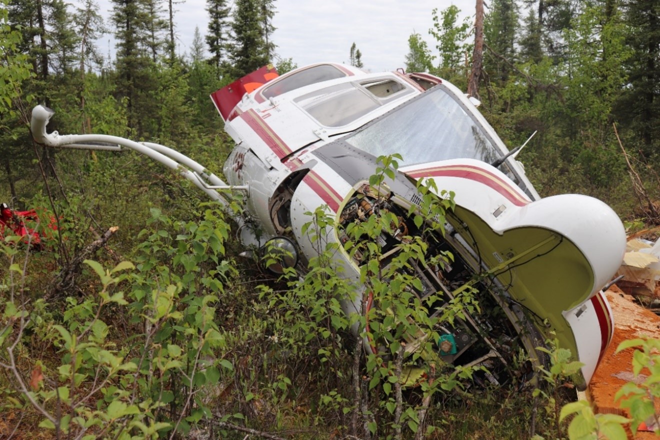
The pilot transmitted a Mayday call on the enroute frequency (126.7 MHz) and informed other aircraft working on the same fire that he had lost tail rotor control. While the helicopter was descending at approximately 1000 to 1500 fpm, the pilot made 3 attempts to use some engine power to fly the helicopter to a suitable landing area near a small lake. He was able to regain some control over the adverse yaw via airflow acting on the vertical stabilizer. As the helicopter descended below treetop height, he raised the collective control to cushion the landing, at which point the low rotor rpm horn activated. At 1924, the helicopter landed on its left skid gear with almost no forward speed (Figure 1). The emergency locator transmitter activated automatically and there was no fire. The helicopter was substantially damaged.
The pilot shut down the engines and electrical systems and was able to climb out of the right-side cockpit door. Another helicopter with fire fighters on board responded to the Mayday call and, within a few minutes, landed near the accident site. The seriously injured pilot was transported directly to a hospital in Thunder Bay, Ontario.
Pilot information
The pilot held a valid airline transport pilot licence - helicopter endorsed for numerous helicopter types, including the Bell 214ST. He had accumulated approximately 8400 hours total flying time, roughly 1940 of which were on the Bell 214ST. The investigation determined that the occurrence pilot met the recency requirements for the flight in accordance with existing regulations. A review of the pilot’s work and rest schedule indicated that fatigue was likely not a factor in this occurrence.
Aircraft information
The Bell 214ST is a twin-engine, single 2-bladed rotor helicopter. The helicopter had no known deficiencies before the occurrence flight.
| Manufacturer | Bell Helicopter Textron |
|---|---|
| Type, model and registration | Helicopter, Bell 214ST, C-GDYZ |
| Year of manufacture | 1982 |
| Serial number | 28109 |
| Total airframe time | Approximately 20 216 hours |
| Engine model (number of engines) | General Electric CT7-2A (2) |
| Maximum allowable take-off weight | 7937.87 kg |
| Recommended fuel types | Jet A, Jet A-1, Jet B |
| Fuel type used | Jet A |
The helicopter had been recently re-assembled upon return to Canada after operating overseas. The work began in February 2021 with test flights commencing 02 March 2021. Once subsequent maintenance and inspections were complete, the helicopter departed HTSC’s base at Ottawa/Carp Airport (CYRP), Ontario, on 01 June 2021, enroute to Dryden Regional Airport (CYHD), Ontario. Daily inspections were carried out while the helicopter was at CYHD. The occurrence pilot picked up the helicopter there and departed for the Nipigon fire base on 07 June 2021.
Tail rotor drivetrain
The tail rotor drivetrain consists of 6 driveshaft segments, 4 hanger assemblies, 3 coupling assemblies, 5 disc assemblies, and 2 gearboxes (42° and 90°) at the base and tip, respectively, of the vertical stabilizer (Figure 2). The coupling assemblies and disc assemblies provide axial and angular flexibility.

Each of the 2 gearboxes is self-lubricated by an internal oil pump and is monitored by a chip detector, temperature switch, and low oil-pressure switch. A separation of the tail rotor drivetrain in front of the 42° gearbox will cause an immediate loss of oil pressure in both gearboxes. As a result, the 42° BOX OIL PRESS and 90° BOX OIL PRESS annunciators on the main warning and caution panel will illuminate.
Figure 3 shows in detail the engine-deck-mounted tail rotor driveshaft hanger and the No. 2 coupling assembly.Footnote 2 The forward flange of the splined coupling (item 15) is bolted to the aft end of the first driveshaft segment. The splined coupling houses, and meshes with, the crowned gear coupling (item 16), which has an output shaft that extends through the seal holder (item 12). The seal holder is retained in the splined coupling via a retainer ring (item 11).

Wreckage and impact information
The helicopter landed on its left skid gear and came to rest leaning to the left on soft, boggy terrain. The skid gear cross tubes had been pushed 2 feet to the right from their normal position in the saddle mounts. The trailing edge of 1 tail rotor blade was damaged; however, there was no indication that the tail rotor was rotating at impact.
The splined coupling (Figure 3, item 15) on the aft end of the first driveshaft segment was found disconnected from the crowned gear coupling (Figure 3, item 16) of the engine-deck-mounted tail rotor driveshaft hanger. The first driveshaft segment exhibited rotational scoring as a result of flailing and consequent contact with components in the fuselage compartment.
A retainer ring (Figure 3, item 11), which should normally secure the seal holder (Figure 3, item 12) and crowned gear coupling within the splined coupling, was found lying loose in the fuselage compartment. The seal holder had exited the splined coupling and was loose on the shaft between the crowned gear coupling and the bearing hanger (Figure 3, item 10).
The No. 1 coupling assembly had remained intact. However the inside face of its seal holder exhibited indentations caused by impact with the teeth of the crowned gear coupling due to the angular displacement of the first driveshaft segment as it flailed within the compartment.
The remainder of the tail rotor drivetrain was contiguous from the crowned gear coupling of the No. 2 coupling assembly to the tail rotor.
The pilot’s seat had remained secured to the cockpit floor. Both pilot seats were equipped with a shoulder harness, but the occurrence pilot felt that it restricted his ability to use the vertical reference bubble window. Therefore, the pilot did not utilize the shoulder harness during long line or slinging operations.
Several items were retrieved from the wreckage for further examination, including 3 warning and caution annunciator panels and the No. 1 and No. 2 coupling assemblies.
The TSB Laboratory analysis of individual lamp filaments from the 3 warning and caution annunciator panels was unable to determine with certainty which, if any, lights were illuminated prior to impact. The magnitude and orientation of the impact forces were not conducive to the creation of large-scale filament damage.
Coupling assembly maintenance
The No. 2 coupling assembly (part number 214-040-604-101, serial number A13-04871) was a component of the engine-deck-mounted tail rotor driveshaft hanger (part number 214-040-600-101, serial number A20-03086). Since its initial installation in November 2015, the No. 2 coupling assembly had undergone regular servicing in accordance with the Bell 214ST maintenance schedule. At the time of the occurrence, the No. 2 coupling assembly had accumulated 1250.1 hours since new and approximately 10 hours since the last servicing.
During the reassembly of the aircraft in early 2021, the 3 coupling assemblies were serviced in accordance with the 500-hour/12-month inspection. They were removed, disassembled, cleaned, inspected, lubricated, and reinstalled on 27 and 28 April 2021. At that time, the occurrence aircraft had accumulated 20 206.1 airframe hours.
All 3 coupling assemblies were serviced by the same aircraft maintenance engineer (AME). Another AME carried out a dual control check (DCC) during the completion of the work. HTSC had adopted the policy of having DCCs conducted after maintenance is performed on drivetrain components. The DCC must be conducted by personnel who have received the required training.Footnote 3
The DCC is also known as a dual inspection or independent check and is to be performed on work that disturbs engine or flight controls.Footnote 4 Rationale and guidance on conducting the inspection is contained in a Transport Canada Airworthiness Notice.Footnote 5 The fundamental component of the procedure is that a “second set of eyes” carries out a careful inspection of the completed work.
Several daily inspections had been carried out before the occurrence flight. However, the Daily Inspection Check Sheet in use at that time by HTSC did not call for an inspection of tail rotor driveshaft coupling assemblies.
Aircraft maintenance engineers
The AME who serviced the 3 coupling assemblies began employment with HTSC in July 2015, as an apprentice AME after completing a Transport Canada-approved AME basic training course. After a 24-month apprenticeship with HTSC, he obtained an AME licence with M1/M2 ratings.Footnote 6 After completing type training courses, he received HTSC aircraft certification authority (ACA) for Bell 206 and 407 helicopters.
The AME who conducted the DCC began employment as an apprentice AME with HTSC in 2014 after completing a Transport Canada-approved AME basic training course. He served a 24-month apprenticeship with HTSC before obtaining an AME licence with an M2 rating. After completing type training courses, he received HTSC ACA for Bell 204, 205, 212, and 214ST helicopters.
Retainer ring
The retainer ring (Figure 3, item 11) is a spiral of approximately 690° made of flat spring steel that seats into a groove machined into the inner diameter of the splined coupling. The retainer ring secures the seal holder, and thus the crowned gear coupling, within the splined coupling.
The dimensions of the retainer ring groove were examined using a coordinate measuring machine, a digital comparator, and optical scanning at a manufacturer’s facility. According to specifications, the retainer ring groove in the splined coupling should be between 0.068 inch and 0.073 inch wide. The retainer ring was 0.062 inch thick. This would result in a free space from 0.006 inch to 0.011 inch between the retainer ring and the edge of the groove.
This suggests that a foreign object, or debris, thicker than 0.011 inch trapped between the spiral layers of the retainer ring could prevent the retainer ring from seating. However, an examination of the retainer ring could not determine whether a foreign object or debris had been trapped between the retainer ring layers.
The occurrence retainer ring was deformed to the extent that the spiral would no longer lie flat. This was likely due to rotational forces and impact with the flailing splined coupling after becoming dislodged. The retainer ring did not appear to be worn, and its outside diameter compared favourably with the exemplar retainer ring.
For an undetermined reason, the retainer ring was dislodged from the splined coupling. Subsequent movement of the main rotor transmission resulted in axial movement of the driveshaft. The seal holder, and ultimately the crowned gear coupling, exited the splined coupling, at which point the tail rotor drivetrain separated. This resulted in the loss of tail rotor thrust, and consequently, yaw control was lost.
The investigation noted that, without the use of a visual inspection aid such as a mirror, or verification with a measuring device, inspection of the installed retainer ring (Figure 3, item 11) is hampered by the proximity of the bearing hanger (Figure 3, item 10).
Loss of tail rotor thrust
The Bell Model 214ST Rotorcraft Flight Manual describes the following effects in the case of a complete loss of tail rotor thrust:
This is a situation involving a break in the drive system, such as a severed driveshaft, wherein the tail rotor stops turning and delivers no thrust. A failure of this type, in powered flight, will result in the nose of the helicopter swinging to the right (left side slip) and usually a roll of the fuselage. Nose down tucking will also be present. The severity of the ships [sic] initial reaction will be affected by airspeed, cabin-loading, center of gravity, power being used, and density altitude.Footnote 7
In the event that the helicopter is in level flight, or a power dive, the following actions are to be taken:
- chop the throttles and reduce pitchFootnote 8 immediately; and
- attain an airspeed slightly above normal autorotative glide speed.
Note: If altitude permits with airspeed above 60 knots, throttle and pitch can be gently applied to see if some degree of powered flight can be resumed. If any adverse yawing is experienced, re-enter autorotation and continue the descent to a landing.Footnote 9
The landing technique is prescribed as follows:
During the final stages of the approach, a mild flare should be executed making sure that all power to the rotor is OFF. Maintain the helicopter in a slight flare and use collective smoothly to execute a soft, slightly nose-high landing. Landing on the aft portion of the skid will tend to correct side drift. This technique will, in most cases, result in a run-on type landing.Footnote 10
On the occurrence flight, at approximately 1600 feet above ground level, the pilot completed these actions when he recognized the loss of tail rotor thrust and was able to slow the spin rate. However, he was committed to an autorotative descent onto the available terrain, which did not lend itself to a run-on type of landing.
TSB laboratory report
The TSB completed the following laboratory report in support of this investigation:
- LP085/2021 – Warning and caution annunciators analysis
Safety action taken
Immediately following the occurrence, HTSC grounded the 3 remaining Bell 214STs in its fleet pending inspection of each helicopter’s complete tail rotor drivetrain to verify correct installation.
A memo was distributed to all pilots reminding them about ensuring sufficient airspeed to maintain helicopter control during an emergency involving the tail rotor or a total loss of tail rotor thrust in cruise flight.
The Emergency Equipment and Procedures Ground Training curriculum now includes training in loss of tail rotor effectiveness and total loss of tail rotor thrust.
The HTSC Bell 214ST daily inspection was amended to require the opening of an additional access panel to facilitate the inspection of the engine-deck-mounted tail rotor driveshaft hanger and the No. 2 coupling assembly.
A 5-page handout was added to the HTSC Bell 214ST aircraft certification authority type training course. The handout emphasized inspection areas and reiterated the requirement for a thorough DCC during the 500-hour/12-month servicing of the 3 coupling assemblies.
Safety messages
As seen in this occurrence, the consequences of an incompletely seated retainer ring entering service can lead to a failure of the tail rotor drivetrain and consequent loss of tail rotor thrust. Therefore, since some components, such as a seated retainer ring, may be difficult to view, the use of visual inspection aids and measuring tools may be warranted during installation and subsequent DCC inspection.
This report concludes the Transportation Safety Board of Canada’s investigation into this occurrence. The Board authorized the release of this report on . It was officially released on .