
Pipeline Investigation Report P00H0061
Natural gas compressor station occurrence
Gazoduc TQM Inc.
East Hereford Compressor Station
Kilometre Post 217,094 on Line 3000
Approximately 80 km SE of Magog, Quebec
East Hereford, Quebec
28 December 2000
The Transportation Safety Board of Canada (TSB) investigated this occurrence for the purpose of advancing transportation safety. It is not the function of the Board to assign fault or determine civil or criminal liability. This report is not created for use in the context of legal, disciplinary or other proceedings. See Ownership and use of content.
-
Table of contents
Summary
At approximately 1724 on 28 December 2000, a release of natural gas resulted in an explosion that destroyed the electrical and services building, heavily damaged the compressor building, and damaged the remaining buildings at the East Hereford compressor station (Kilometre Post 217,094) on Line 3000 of Gazoduc TQM Inc. Before the occurrence, the station had been shut down since approximately 1004 due to an unintentional manual initiation of the station's emergency shutdown system. Following the emergency shutdown of the compressor station, a maintenance person was sent to the station to reinitiate the electric motor-driven compressor unit. During the day, after repeatedly trying to get the station into the ready state mode to return the station to normal pipeline operations, an explosion occurred. The on-site maintenance person was seriously injured.
1.0 Factual information
1.1 The accident
At approximately 1004 eastern standard timeFootnote 1on 28 December 2000, the Gazoduc TQM Inc. (TQM)Footnote 2compressor station, located at East Hereford, Quebec, comprising a single electric motor-driven compressor unit, was shut down by an unintentional manual initiation in the station yard of the emergency shutdown (ESD) system by a member of the general public accompanying a snow removal contractor. Initiation of the ESD system caused a blowdown of all the high-pressure natural gas piping within the station. Natural gas from the station piping was vented to atmosphere through the vent stack located within the fenced-in area of the station. Up to that point in time, the station had been operating normally at or near the full-rated capacity for the pipeline. With the initiation of the ESD system, all valves functioned per design, permitting a controlled venting of the gas in the station piping to atmosphere.
At the time of the ESD, the East Hereford compressor station had been in service for approximately one year, with an initial startup date of 17 December 1999 (Appendix A shows a system map of the TQM facilities). The station was equipped with a single electric motor-driven compressor unit, commercially referred to as a MOPICO (motor pipeline compressor), model No. RM40. The warranty terms of the MOPICO were 10 000 hours (operational hours), or 18 months from startup, or 36 months from readiness for shipment from the manufacturer, whichever came first. Based on these numbers, the East Hereford unit would still have been under the warranty period at the time of the incident. Since the market downstream of the compressor station was not yet fully developed, the compressor unit was used on an intermittent basis; that is, whenever the downstream demand reduced, the internal pressure of the pipeline fell below preset internal pressure set points, and the MOPICO would operate to supply additional natural gas at pipeline pressure.
On the day of the occurrence, which was also the Christmas holiday season, the station was remotely controlled from the Calgary Gas Control Centre (GCC) of TransCanada PipeLines Limited (TCPL), with TQM's Montréal GCC closed for this period. As part of normal procedures, monitoring was performed by the GCC during normal off-hours and weekends on a year-round basis. Following the unintended ESD, the control centre contacted the TQM person on call in Magog, Quebec, regarding the East Hereford shutdown. A TQM maintenance person was notified and deployed to get the compressor unit back on line.
The maintenance person carried out an initial inspection of the grounds and exterior ESD switch point units to ensure that the station was secure and the units were reset to their normal position. (See Appendix Bfor a plot plan of the East Hereford compressor station.) Visual inspection of the graphical representation of the pipeline valves in the station's local control centre determined that a number of solenoid valves associated with the station valves were in a "trip" state, and that there was no pressure between the valves. These valves were determined by the maintenance person to be frozen and needed to be thawed and reinstalled. Numerous attempts to reinitiate the operational sequence between the station valving and the electric motor-driven compressor unit to return the station to a ready state mode for normal pipeline operations were unsuccessful. Since the station piping had been vented of all natural gas, repressurization of the station piping became a priority, resulting in further thawing and reinstallation of frozen solenoid valves.
At 1306 and unannounced to the on-site TQM maintenance person, the station's Main Line Block Valve (MLBV) was in the fully open position to maintain gas service, having automatically moved from the fully closed position when the MLBV sensed that pipeline pressures downstream of the station had fallen below a preset pressure level. Since the station was shut down, the MLBV was designed to automatically open to allow full line pressure natural gas to bypass the station, repressurizing the downstream section to established service levels to maintain delivery capabilities to downstream customers. Once repressurized, the MLBV would return to the fully closed position. The opening and closing of the MLBV would occur several times during the day.
At 1446, during one of the reinitiating attempts by the on-site TQM maintenance person to get the station to a ready state mode, together with a simultaneous repressurization of the station piping, the local-based Supervisory Control and Data Acquisition (SCADA) system produced a high/high-pressure alarm of over 40 kPa, which was transmitted through the main SCADA system to both the Montréal GCC (actually located at Repentigny) and the Calgary GCC. The TQM maintenance person investigated the situation in the electrical and services building (ESB), which housed the local-based SCADA system, and determined that the high/high-pressure alarm originated in the terminal junction box (TJB) for the electric motor-driven compressor unit. This alarm had initiated a unit STOP with no venting of the gas and locked out the electric motor. Before the initiation of the STOP, the station and unit purge valves, as well as the unit vent valve and the MLBV, were open. The station discharge blowdown valve stayed closed. (Appendix D shows a schematic of station piping, valves and associated equipment.) The Calgary GCC made several unsuccessful attempts to contact the TQM maintenance employee.
At 1454, the MLBV automatically returned to the fully closed position, having opened at 1306 once the downstream section of the pipeline system had reached a pre-determined pressure level. At 1534, the MLBV returned to the fully open position and then fully closed position at 1553.
At 1605, the local SCADA system produced a second high-pressure alarm of over 20 kPa but less than 40 kPa in the TJB, which was also transmitted to the Calgary GCC through the SCADA system. The maintenance person identified that there was a gas leak in the vicinity of the TJB and requested further assistance from his supervisor. However, the overhead gas detectors did not identify the presence of any escaping natural gas in the compressor building. At this time and unannounced to the on-site TQM maintenance person, the MLBV was once again in the fully open position, having automatically moved to this position at 1602, and remained fully open to make natural gas deliveries to downstream customers until after the occurrence. Also at this time, the station discharge blowdown valve, the unit purge valve, the unit vent valve, and the recycle valve were open. The station purge and station discharge purge valves stayed closed.
At 1724, while the maintenance person carried out further checks, including resetting various pieces of equipment within the ESB, an explosion occurred. At this time, the MLBV, the recycle valve, the station discharge blowdown valve, and the unit purge valve were open, while the station purge valve and the station discharge purge valve were closed. Two fire balls were witnessed by local residents living in the vicinity of the station. Events at the station shut down the electrical power grid in the East Hereford district. At 2026, electrical power was returned to local residents, approximately three hours after the occurrence.
At 1729, the Sûreté du Québec (Quebec provincial police) received an urgent call from a local resident, advising of the situation at the station. At 1730, the fire chief of the Bleecher Falls (New Hampshire, U.S.) Fire Department received notice of an emergency situation on the Canadian side of the international border. In accordance with mutual aid agreements between Canada and the U.S., the fire department responded to the occurrence, arriving on site at 1735. The fire department immediately established a command post, rerouting highway traffic adjacent to the station. During this time, the Calgary GCC experienced a complete loss of SCADA system signals from the station and notified TQM maintenance personnel. At 1810, two Bleecher Falls firefighters, equipped with natural gas detectors, entered the station. Moments later, hearing a sound emanate from the wreckage, they discovered the injured TQM employee under a pile of debris. At 1830, other TQM employees arrived at the station. At 1840, the employee was removed from the wreckage. At 1850, on-site TQM personnel confirmed to the Bleecher Falls firefighters that there were no other natural gas leaks in the station. At 1901, an ambulance transported the injured TQM employee from the site.
An initial site investigation immediately following the accident indicated that a natural gas explosion had occurred in the ESB. The epicentre of the blast was located in or adjacent to the emergency generator and electric heating and ventilation system located at the back of the building. The ensuing explosion and fire damaged the ESB and other buildings in the station. Natural gas had migrated into the ESB in sufficient quantities to create an explosive mixture that had ignited, probably by a spark from an electric device in the epicentre of the blast.
On 08 February 2002, the East Hereford station was returned to normal service after being completely rebuilt. The original electric motor-driven compressor had also been examined for any deficient parts, which were rebuilt or refurbished, before being fitted with a new Passthru flange, Passthru elements and 24 new O-ringsat the request of the end-user. The electric motor-driven compressor was then reassembled and reinstalled at the station.
1.2 Injuries
As a consequence of this accident, one TQM employee suffered second-degree burns to the face, hands, mouth and lungs along with minor cuts and bruises.
1.3 Damage to equipment - Product lost
Damage to TQM's East Hereford station was extensive. The main components were completely destroyed or damaged as follows:
- a compressor building that housed the electric motor and compressor, together with associated piping and an oxygen measuring unit (building to the left side of photo);
- the electrical and services building (ESB) that housed the local control room, the electrical room, the variable-speed motor control room, together with several smaller rooms for emergency power, kitchen, workshop, and heating and ventilation system (building to the right side of photo);
- the measurement telemetry control building;
- the measurement building; and
- various types of electrical equipment, such as computers, electrical switchgear, and the electrical transformers with associated electrical and control wiring.

The MOPICO (motor pipeline compressor), jointly built by ALSTOM and MAN Turbomaschinen (formerly Sulzer), a motor and compressor unit together with associated piping and valve systems, used to compress the natural gas stream at the station, suffered no visible damage. Due to the extent and scope of the damage, it was not possible to recover any historical operational data from the local computer-based SCADA systems. However, limited operational data were recovered from the main SCADA systems of TQM's GCC in Montréal and from TCPL's Calgary GCC. The data showed principal pipeline values from the station's operational history before the occurrence.
In addition to the station facilities damaged or destroyed during the explosion, commercial buildings and residential homes in the immediate vicinity experienced surface and structural damage, arising mainly from flying debris and the after-effects of the shock wave from the explosion. The site was subsequently cleared of all debris, the compressor building and ESB were removed, and new station facilities were built.
The volume of natural gas lost through the Passthru flange on the day of the occurrence was not measured. Assuming an even distribution of natural gas within the ESB, the volume of methane needed for deflagration would be 75 m³, based on its lower explosive limit (LEL). If the upper explosive limit (UEL) was considered, then the maximum volume of methane for deflagration would be 197 m³. A detailed site analysis of the ESB determined that there was incomplete deflagration; natural gas was not evenly distributed inside this building. A structural examination revealed that, in one part of the building, the gas was just reaching the LEL and, in another part of the building, it was over the UEL. It is estimated that the volume of natural gas that migrated from the compressor building over to the ESB was in the range of 40 m³to 400 m³.
1.4 Weather
On the morning of the occurrence, skies were clear, the outside temperature was −15.2 °C, and winds were out of the south-southwest at 9 km/h as recorded at Lennoxville, Quebec. At 1700, there was a very light snow fall, the outside temperature was −13.1 °C, and winds were out of the south-southwest at 8 km/h.
1.5 Particulars of the pipeline system
The TQM pipeline system commences at Saint-Lazare, Quebec, where the TCPL system delivers natural gas from the western Canadian sedimentary basin, which is then delivered through one of TQM's two high-pressure pipeline systems to Québec, Quebec, and all points in between. TQM delivers gas on a second high-pressure pipeline to New Hampshire, U.S. Referred to as Line 3000, this pipeline receives natural gas at Terrebonne, Quebec (previously Lachenaie, Quebec), and transports it to East Hereford for delivery to Portland Natural Gas System (PNGS), which then delivers the gas to consumers in the eastern U.S. market see (Appendix A). The National Energy Board (NEB) had granted a maximum allowable operating pressure of 9928 kPa for Line 3000. During normal operations, the operating pressure of this pipeline varies between 4000 kPa and 9928 kPa. The initial date for in-service operation of the East Hereford station was 17 December 1999.
Two compressor stations were constructed on Line 3000 at one-year intervals. The initial station is located at Terrebonne and the second station, at East Hereford, located at Kilometre Post (KMP) 0,000 and KMP 217,094 respectively. Both stations are equipped with single ALSTOM electric motor-driven compressor units (MOPICO), model No. RM40, both rated for 7.0 megawatts (MW). For continuity of service, TQM maintains a spare electric motor at Repentigny. At the Lachenaie station, TQM has a 7.0 MW-rated variable frequency drive (VFD) output for the MOPICO unit installed, and at the East Hereford station, there is a 3.2 MW-rated VFD output for the unit. At the East Hereford station, the electric drive motor was fabricated by ALSTOM in Belgium. The two compressor units were fabricated by Sulzer in Switzerland, and these components were assembled on site at East Hereford. The MOPICO has been in pipeline service since the early 1990s in Canada, the U.S. and Britain. The MOPICO, which has been approved by CSA International, provides many benefits over gas turbines, such as smaller size, flexibility of operation, quiet operation, and robustness.
Before commencing pipeline operations, TQM was granted a "Leave to Open" by the NEB. In accordance with its mandate under the Canadian Electrical Code(CEC), the Régie du bâtiment du Québec(RBQ) performed a detailed site inspection of all electrical and electronic instrumentation systems installed at the East Hereford station before the introduction of electrical power into the station. TQM was required to address any electrical deficiencies identified by the RBQ before the introduction of electricity into the station and commissioning, testing, and normal pipeline operations.
1.6 Compressor station description - Design, construction and operations
The East Hereford station was designed and built as a "turnkey" project. TQM hired a consortium formed by an engineering firm and a construction contractor to design, specify, and supervise construction. The engineering consultant's activities included all civil, mechanical, electrical, and electronics engineering, the tendering process, and the final selection process. The consultant was also responsible for design, specification, procurement, and installation of all mechanical, electrical and electronic equipment, as well as the establishment of two new buildings at the station - the compressor building and the ESB. During construction, the engineering consultant provided supervisory and inspection personnel on site to ensure adherence and conformity to the approved design packages. Once construction was complete, the facilities went through a comprehensive commissioning phase to ensure the station would operate as designed. Upon successful commissioning, the station was turned over to TQM as a completed project. This station was designed to meet the technical requirements of Canadian Standards Association (CSA) standards entitled CAN/CSA-Z662, Oil and Gas Pipeline Systems(CSA Z662) and CAN/CSA-C22.1, Canadian Electrical Code.
As with all construction projects, each discipline was managed individually and jointly on a day-to-day basis by an overall project manager from the consortium. The main project manager control mechanism was a set of approved construction drawings and associated specifications, which formed part of the bid package that had previously been issued for tender. From start to finish, the project manager supervised the activities of a site foreman and site inspectors. During construction, the project manager was kept abreast of every event, so that unforeseen situations could be rectified quickly and efficiently. However small, any and all variations from the approved drawing and specifications were brought to the attention of the project manager for final sign-off.
After construction of the main buildings, the task then became one of pulling and installing electrical power wiring and various types of instrumentation cable runs to support the MOPICO and compressor station operations. Electric power entering the station was routed to the TJB through an on-site transformer, a VFD converter through a switch gear, and two 3.5-inchTeck cables. The three-phase Teck cable power conductors were then affixed to individual terminal connection points inside the TJB. CEC requirements for attaching and sealing the Teck cables at the bottom of the TJB had been identified. The consultant had specified the use of two specially designed and built explosion-proof fittings for both ends of the Teck cables for use in hazardous areas. However, in its design, the consultant did not specify the use of the supplier's recommended sealing compound. The sealing compound was recommended by the supplier of the fitting. Further, the consultant did not specify any type of sealing mechanism for the two Teck cables to protect against continuous pressure buildup inside the TJB.
Only two types of sealing compounds are approved by the CSA and Underwriters Laboratory Inc. (UL) for these fittings. This information is clearly indicated by the supplier as follows:
- on the fitting carton label;
- on a red tag attached to each fitting with an elastic band; and
- on the installation instructions sheet provided with the fittings.
The carton label clearly indicated that sealing compounds are not included with the fittings and had to be purchased separately from the supplier of the fitting. However, neither of these sealing compounds was rated to meet the continuous pressure buildup requirements of the TJB as specified by the supplier of the MOPICO.
The final station, which included the gas metering facilities built in 1998 in a separate project, comprised the following buildings see (Appendix B) in a fenced-in area:
- the compressor building;
- the electrical and services building (ESB);
- the telemetry control building; and
- the measurement building.
The compressor building, which contained the MOPICO and associated valves and piping, was designed to conform to CEC requirements for a Class I, Division 2, Group D hazardous area location. The compressor building was equipped with a natural gas detection system, which would initiate an immediate shutdown of the station, together with venting natural gas from all piping within the building in the event of a detectable release of gas. This building was also built in accordance with the requirements of Section 4.10 of CSA Z662, which contains similar conditions regarding the shutdown and venting of station piping.
The ESB, located some 15 m from the compressor building, contained, among other items, electrical and local-based SCADA control equipment. In addition to a lunch room, washroom, and the heating and ventilation system, this building also housed the solid state electronic VFD system, and system control and associated operational backups for the local SCADA system. As this building did not have any natural gas lines entering it, it did not have a natural gas detection system installed. As per the requirements of the CEC, the building was designated as gas free, and there were no regulatory or other code or standard requirements that dictated that a gas detection system be installed. However, Section 4.10.1.3.1 of CSA Z662 stipulates that sufficient ventilation shall be provided so that employees are not endangered, under normal operating conditions within normal work areas, by an accumulation of hazardous concentrations of flammable or noxious vapours or gases.
The MOPICO unit is an integrated, hermetically sealed motor/compressor unit. It comprises an asynchronous, high-speed electric drive motor complete with two drive-shaft ends, onto each of which a compressor impeller is mounted. (Appendix C for a schematic of the MOPICO unit and associated assembly of piping for the compressor.) Depending on the required duty, these impellers can be connected either in series or parallel by an external pipe/valve system. At the East Hereford station, the impellers operated only in series to produce the required output pressure. The sealed MOPICO unit is cooled by natural gas taken from piping after the first-stage pressurization, at the midway pressure between the compressor suction and discharge pressures. The high-frequency motor is driven through a solid state electronic VFD, which was located in the ESB. All motor control cables originated in the ESB and terminated within the Class I, Division 2 compressor building.
An integral part of the MOPICO motor/compressor unit is the Passthru flange, a high-pressure sealing flange between the motor and the TJB. The fitting shown in Appendix E does not form part of the MOPICO, but is the physical means for power delivery from the ESB. The Passthru flange mechanically seals and permits electrical connections from the TJB, which operates at atmospheric pressure, to the electric motor, which operates at the midway pressure between compressor suction and discharge pressure. It is built of stainless steel and features 12 specially designed Passthru penetrations, through which an electrical conductor passes. Referred to as a "Passthru element," each electrical conductor consists of two O-ringsmade of a synthetic, flexible compound called Viton-Type "A" (Viton), a copper rod, a long brass outer ring, and an epoxy filler. Each Passthru element is used to conduct electric power to the motor from the connection points inside the TJB. Each Passthru element is designed to fit into one of the Passthru flange penetrations to form a tight, mechanical seal that is further protected from any gas leaks by the two Viton O-rings.
During the period of 29 May to 30 May 2001, a detailed examination of the East Hereford MOPICO in Houston, Texas, U.S., revealed that there were no manufacturing deficiencies with the MOPICO related to the rotor, the stator, the motor housing, the compressor housing, and the compressor casing. However, the Passthru flange contained deficiencies with respect to the diameter of the Passthru flange penetrations. All 12 penetrations were found to be beyond manufacturing tolerances stipulated by the motor supplier company. The penetrations increased in diameter from the TJB side to the motor side of the Passthru flange. Each Passthru element was checked against company specifications. Deficiencies were noted, especially related to the depth of the two grooves into which the Viton O-ringswere seated. However, over-tolerances of the Passthru flange penetrations, together with under-tolerances in the depth of the Passthru element grooves and the O-ringsealing system provided little or no sealing capability for 10 of the 12 Passthru elements, making the Viton O-ringsealing system ineffective during post-accident field testing of the assembly with nitrogen gas.
Prior to the occurrence and the electric motor being assembled, the assembled Passthru flange successfully passed a pressure test up to 1.5 times the design pressure. After the occurrence, the same Passthru flange assembly was retested several times at the East Hereford compressor station and leaking of this assembly was noted. In France, the same Passthru flange assembly was retested in a liquid oil bath and leaking was again noted. However, when 24 new Viton O-ringswere greased, then fitted onto the greased Passthru elements and then refitted into the Passthru flange for reassembling purposes, it was noted that the Passthru flange assembly did not leak. The lack of leaking was possibly due to the hydrosealing effect of the greased parts in the liquid oil bath during testing. Sometime after the assembly was put into service, the hydrosealing effect would have been lost due to the combined effects of the operating temperature of the electric motor and any leakage of the natural gas stream, which contained corrosive trace elements.
The design of the MOPICO called for Viton O-rings. A limited laboratory analysis of eight O-ringsdetermined that 50 per cent of those tested were made of a rubber compound, instead of Viton. This explained weight variations found in the complete package of 24 O-rings, which were tested against specifications. (Appendix Fshows a table of physical measurements and physical conditions of the O-rings.)
Since any mechanical seal system can be subject to failure, the MOPICO unit was designed and manufactured with backup safety features against any potential Passthru flange seal system failure. In a case where a leak of natural gas occurred across the Passthru flange and around the Passthru elements, the buildup of natural gas pressure within the TJB would be sensed by a pressure transmitter fitted on the side of the TJB. Once a preset pressure of 40 kPa was registered, the pressure transmitter would send a high/high-pressure signal to the local SCADA system, which would automatically shut down and isolate the MOPICO until the high/high-pressure condition did not exist. An alarm would sound in the station and natural gas would be vented from the motor through the station's vent stack. The high/high-pressure TJB alarm signal would be issued through the main SCADA to the GCC. TQM had decided to alter the design of the safety feature when the unit was installed and before its being placed into operation. The pressure transmitter shutdown design was changed such that, when gas was detected by the pressure transmitter at 40 kPa within the TJB, a blowdown or venting of the MOPICO would not occur as was originally intended by the MOPICO manufacturer. For the TJB to maintain any buildup of internal pressure to ensure activation of the pressure transmitter, the sealing mechanism for the two Teck cables required a system that was rated for continuous pressure, which was not specified by the consultant responsible for the design of the station. Until the pressure buildup had been investigated and the reason for the leak acted upon by company officials, the SCADA system would not permit the MOPICO to be restarted. This pressure detection method was certified by CSA International as outlined in CSA technical information letter (TIL) E-20, MOPICO CSA Special Acceptance. At the time of certification, an oxygen sensing unit was also installed on the pipework as a condition of CSA approval to ensure that the electric motor cooling gas was oxygen free, which is a permissive signal for the start of the unit pressurizing cycle.
While the TQM maintenance person was inside the compressor building attempting to reinitiate the unit to get the station to a ready state mode, the employee could hear the sound of leaking natural gas around the TJB. Because the TJB was fitted with an electronic pressure transmitter that could read pressures up to 690 kPa, the resulting electronic pressure signal was forwarded into the adjacent ESB. There was no mechanical means of venting the TJB and no mechanical or electronic display of the actual internal pressure of the TJB from inside the compressor building. Similarly, there was no mechanical, chemical or electronic means of determining if gas was present inside the TJB. While prohibited by the provisions of CSA TIL E-20, there were theoretically a number of potential locations where gas could possibly leak out (the two electrical fittings affixed to the bottom of the TJB, the flanged connections at the back of the TJB and the entry door to the TJB), thereby causing a lower pressure in the TJB and reducing the ability of the pressure transmitter to function as intended. It should be noted that any gas leaking from the TJB would have been detected by the overhead gas detection system for the compressor building, which would have initiated an emergency shutdown of the station and vented the station piping of gas. During field testing after the occurrence, minor leaking was noted at test pressures of 100 kPa.
Electric power for the MOPICO entered through two high-tension power lines that were connected to the station main power transformer. The power was then routed to the compressor through an open and easily accessible cable raceway from the transformer through the switch gear and the VFD. The two Teck cables were attached to the bottom of the TJB. Three-phase power conductors were affixed to individual terminal connection points inside the TJB. During the design stage, the engineering consulting firm identified CEC requirements for attaching and sealing the Teck cables at the bottom of the TJB to protect against any potential exploding natural gas from migrating. The consultant had specified the use of two fittings. These devices did not form part of the equipment provided by the MOPICO supplier, but part of a package to be installed by the electrical contractor during installation of the two Teck cables and other electrical and electronic cables, fittings and equipment. For safety reasons, an intermediate electrical switchgear was installed in the ESB to permit a safe and effective means of isolating the MOPICO and other pieces of electrical equipment from the transformer during periods of repair and operation.
The fitting design was approved by both the CSA and UL for use in Class I, Division 2, Group D hazardous areas. This design provides a number of special features for connecting and disconnecting the Teck cables from the TJB during maintenance and general servicing. First, the fittings safely anchor the two Teck cables to the bottom of the TJB. Once secured to the TJB, the Teck cables can be easily disconnected for maintenance and reconnected without a major reinstallation process. Second, the fittings also furnish a seal where the cables enter the TJB. While these fittings were not designed to be gas tight, the seal at the ends of Teck cables was designed to inhibit or prevent an explosion inside the TJB from migrating through the Teck cables, thus preventing an extension of a dangerous situation into the ESB. The fitting was designed to diffuse hot gases in a controlled manner, which lowers the temperature, thereby preventing explosions inside an enclosure from propagating to atmosphere outside the enclosure. However, the fitting was not designed for continuous pressure service, as was the case with the TJB. Since there was no effective means of preventing any buildup of hot or cold gas from migrating out of the TJB along the two Teck cables, the pressure transmitter would not function as intended.
In accordance with CSA and UL certification for this fitting, two types of sealing compound were recommended by the connector's supplier in documentation included with each fitting. The sealing compounds were sold separately. Neither of the two recommended seal compounds were rated for continuous pressure service. The TJB fittings and switchgear cables were not part of the MOPICO supply contract. This equipment was specified by the engineering consultant who subcontracted the supply and installation to the electrical contractor. The electrical contractor further subcontracted the wire terminations of the fitting/Teck cable assemblies to a specialized firm.
Extensive field and laboratory tests were carried out after the accident. Detailed field tests performed on the MOPICO using nitrogen as the testing medium determined that the Passthru flange leaked around several of the Passthru elements. The door of the TJB and flanged connections located at the back of the TJB were checked at low pressure and no substantive leaking of nitrogen was identified. However, nitrogen flowed freely past the seals of the fitting/Teck cable assemblies, and migrated into the Teck cables. Once inside, nitrogen could then flow freely along the Teck cables from the compressor building to the ESB. It was also noted that one Teck cable permitted a higher flow rate than the other.
During a laboratory test, the TJB was inspected to identify any surface and structural damage that could indicate a potential escape route for natural gas. There was no surface or structural damage noted on the TJB, the door and the associated flanged connections located at the back of the box. The two fitting/Teck cable assemblies from the bottom of the TJB and the associated pieces of Teck cables were visually inspected and then each was physically dismantled by machine sawing through each assembly lengthwise. One of the two fitting/Teck cable assemblies did not have the recommended sealing compound and it had been improperly installed. The inner jacket of the cable was not skinned off to expose the conductors in the sealing chamber of the fitting as stated in the supplier's instructions, and a felt barrier had not been placed in the assembly. A chemical analysis determined the material to be "Chico," a commonly available material used in the electrical industry in Canada. While there had been an attempt to install a felt barrier, the second fitting/Teck cable assembly had no sealing compound. A felt barrier is installed before any sealing material to hold the material in place until it solidifies. In both cases, the entry points into the bottom of the TJB were covered by another sealing compound, which is normally used to protect against the progression of a flame and is referred to as "flame guard." An inspection performed during laboratory testing determined that it had been poorly installed and did not provide any sealing capability.
At the opposite end of the two Teck cables, where they enter into the ESB, two other 3.5-inchfitting/Teck cable assemblies were visually examined. These two assemblies did not have any seals at the point of entry into the ESB. After the completion of construction and before the startup date, the station had been inspected by the RBQ, a provincial agency responsible for ensuring conformity with CEC standards. During these inspections, the lack of appropriate seals for the fitting/Teck cable assemblies was not identified.
The CEC required sealing the end of the Teck cables at the point of entry of the fitting/Teck cable assemblies into the TJB. However, the CEC did not require sealing the opposite end of the Teck cables in a location that was non-certified, even though the ESB was located in a fenced-off area that had been designated as a Class I, Division 2 hazardous area. The technique used by the CEC and other international electrical codes is to prevent gas from entering the Teck cable in the hazardous area. Since the Teck cable has a continuous outer sheath, gas can only enter the Teck cable at the termination point. Even though seals designed for continuous pressure when only one termination point is located within a pressurized enclosure such as the TJB are commercially available, the CEC does not require their use.
At the occurrence site, the same type of fitting, although smaller in size, had been employed extensively around the compressor station to meet CEC sealing requirements in hazardous areas. Application of the supplier's recommended sealing material had been made by the electrical contractor. For approximately 50 per cent of these other smaller fitting assemblies, the sealing material was improperly installed, rendering the seal ineffective. After completion of this construction work and before the startup date for the station, these additional fittings had been inspected by the RBQ to ensure conformity with the CEC. During these electrical inspections, inappropriately installed seals for these smaller fitting assemblies within the compressor building were not identified.
1.7 Supervisory control and data acquisition - Main and local systems
The pipeline system, together with associated compressor and meter stations, was designed so that pipeline operations could be remotely controlled from either Montréal (actually Repentigny) or Calgary through a SCADA system. The same level of control existed at each facility in the pipeline system. On the main system, a limited amount of key TQM operational data were made available and collected and stored for future retrieval at the GCCs in Montréal and Calgary. However, the majority of operational data for East Hereford was only collected at the station. These data provided insights into the operational history of every component in the station. A local-based SCADA system was installed for data collection and management purposes.
On the day of the occurrence, the detailed and complete history of station operations and alarms for the MOPICO, all station yard valves, and all other station-related equipment and associated activities was stored on the computer-based local SCADA system. Under normal operating conditions, key portions of the local SCADA information were telemetered to the Calgary and Montréal GCCs, Montréal being the principal GCC for pipeline operations. Since the station was being remotely controlled only from Calgary, only key Calgary-based decision-making information was telemetered through the national SCADA system. As a result of this occurrence, a complete operational history of equipment and personnel activities for the day was destroyed. Several attempts were made to recover local SCADA system operational data from computer hard drives recovered at the site. These attempts were unsuccessful.
With the incomplete and limited historical data available from Calgary and Montréal, the investigation manually reconstructed the events of the day. Before the ESD, all operations and functions had been normal for the previous 24 hours and no abnormalities in operating conditions were identified from this review. After the ESD and for the 7.5 hours preceding the accident, the reconstructed records are as follows:
- 1004 ESD of compressor station;
- 1004 to 1005 shutdown sequence is complete with the closing of the unit vent valve;
- 1218 TQM technician is on site and disarms the security system;
- 1218 to 1445 several attempts to reinitiate the MOPICO and to return the station to a ready state mode;
- 1306 to 1454 MLBV moves to the fully open position, permitting full line pressure gas to move past the station, and then fully closes;
- 1446 first high-pressure gas alarm in the TJB, while MLBV is fully open;
- 1446 no venting of unit and piping and no lockout of MOPICO;
- 1447 to 1601 several more attempts to reinitiate the MOPICO and to return the station to a ready state mode;
- 1602 MLBV moves to the fully open position, permitting full line pressure gas to move past the station and then remains open;
- 1605 second high-pressure gas alarm in the TJB;
- 1642 unit purge valve moves from open to closed position; and
- 1724 all communications with the station is lost.
A copy of the reconstructed time line of events from the East Hereford compressor station log can be found in Appendix G. The SCADA system was set to record all operating pressures of 2400 kPa and above. Pressures under 2400 kPa were not recorded, which prevented the Calgary GCC operator from determining whether a section of pipe in the station had been completely vented of natural gas. While undertaking the task of reinitiating the station, the TQM technical/maintenance personnel did not have ready access in the area of the TJB to any mechanical or electronic pressure gauges or readouts that would indicate whether there was any pressure in the piping.
1.8 Valve operations and the emergency shutdown
As with all motive-powered stations in Canada, the safe and efficient management of hydrocarbon product through a pressurizing unit is arrived at through valves, whether automatic or manual. A variety of valves had been installed on the inlet and outlet piping for the station. In addition, valves had been installed for isolation purposes during maintenance periods as well as for venting the pipes during maintenance and emergency periods.
These valves were electrically or pneumatically connected to, and managed by, the pipeline's local SCADA system. Operation of the valves permitted natural gas to enter or exit the MOPICO and associated station piping quickly and safely. Each automated main line and station valve was fitted with an electromechanical operator, which permitted the valves to be controlled and managed either locally or remotely by the SCADA system. A key component of the automated, remotely operated valve is a small-diameter solenoid valve. Energizing the solenoid valves would create the gas pressure to open and close the valves. Any malfunction with the solenoid valves will render the valve inoperable. For those situations, TQM maintenance personnel were instructed to go to the station and repair the solenoid valve.
On 28 December 2000, the station valves were not operating as designed. A number of the solenoid valves were frozen in place, requiring that the valve be removed, thawed, and then reinstalled. When completely thawed, a large volume of water drained from the solenoid valves. In an attempt to reinitiate the MOPICO and return the station to a ready state mode, four solenoid valves were removed, thawed and reinstalled at various times during the day. During the design stage of the station, the engineering consultant did not require the installation of heat tracing, a means of avoiding frozen solenoid valves, because the gas analysis showed only trace amounts of water in the gas stream.
At East Hereford, various levels of emergency controls had been designed as follows:
- Emergency shutdown (ESD):the response to an uncontrolled condition at the station, initiated by an operator or an alarm as defined in the station's Shutdown Cause and Effect Matrix. It brings the MOPICO to a full emergency stop by tripping the VFD and then opening the station blowdown and unit vent valves after closing the station's inlet and outlet valvesto evacuate natural gas in the station yard and MOPICO unit piping;
- Emergency unit blowdown (EUBD):the response to an uncontrolled condition at the station, initiated by an operator or an alarm as defined in the station's Shutdown Cause and Effect Matrix. It brings the MOPICO to a full emergency stop by tripping the VFD and then opening the unit vent valves after closing the MOPICO's inlet and outlet valvesto evacuate natural gas in the MOPICO unit piping only; and
- Normal stop (STOP):the response to a controlled condition initiated by an operator or an alarm as defined in the station's Shutdown Cause and Effect Matrix. It brings the MOPICO system to a stop by commanding the VFD to stop after slowing the motor down to 6000 rpm. The control logic sequence then puts the station in a ready-to-start mode. The VFD is not locked out and the unit is not vented.
As one of several safety features, the electric motor-driven compressor unit cannot be reinitiated until the source of the alarm has been rectified and the ready state mode for the motor startup has been achieved. On the day of the occurrence, the MOPICO 's electric motor, compressor casing and its associated piping remained pressurized following a STOP.
The ESD system was designed and built to conform to the regulatory requirements of Section 4.10.2.4, Emergency Shutdown Facilities, of CSA Z662, as required by one of the conditions of NEB's certificates authorizing construction, and was granted "Leave to Open" by the NEB. This section dictates that a compressor station shall have ESD systems that, among other requirements, block gas out of the station and blow down the station's piping. The blowdown piping shall extend to a location where the discharge gas will not create a hazard to the compressor station or surroundings. The dual shutdown systems (ESD versus EUBD) at the station conformed to CSA requirements and the applicable company standards and practices. The STOP feature did not conform.
Design of the operational actions of the station's valves, together with design parameters for an ESD and an EUBD, were set out in two company tables, referred to as the Shutdown Cause and Effect Matrix and the Analog Calibration and Alarm Settings for the Station. A detailed review of these tables and drawings did not identify any sequencing errors for an ESD. However, since the start of normal pipeline operations, the shutdown cycle had been modified by TQM to retain gas inside the MOPICO; thus no venting took place. Referred to as NORMAL STOP or ESTOP (unit stop), this condition was included to stop the compressor unit without venting of the gas. These two tables did not address this situation. In addition, the tables did not address a situation where the station operator valves are frozen and rendered inoperable because of a malfunction with the solenoid valve. Operational procedures should have been available to cover frozen valves or to address a mechanical malfunction of the station valves. On the day of the occurrence, the valving sequences for the station only functioned properly when the ESD was initially pushed at 1004.
1.9 Analysis of natural gas stream
Once product is received from the TCPL system at Saint-Lazare, TQM delivers it through its two high-pressure pipeline systems to its many customers. As illustrated in the General Terms and Conditions of the TQM Pipeline Tariff, a detailed breakdown of the TQM gas stream is as follows:
- methane is the principal component in a range of 95 per cent of volume;
- ethane is the secondary component in a range of 2.5 to 2.8 per cent of volume;
- propane, isobutane and butane are present in trace quantities;
- nitrogen and carbon dioxide are also present at a volume of about 1.5 to 1.8 per cent and 0.6 to 0.8 per cent respectively;
- water is also present in trace amounts; and
- sulphur compounds are also present in trace amounts at a level not exceeding 23 mg/m³for hydrogen sulphide and 115 mg/m³for total sulphur.
Additional gas samples taken by the company on 04 December 2000 at Berthierville, Quebec, and in March 2000 at Emerson, Alberta, over a 31-dayperiod to ascertain the amount of sulphur and hydrogen sulphide gas in the natural gas stream of TQM determined the following values:
- total sulphur (mainly hydrogen sulphide) was found to be in a range of 1.7034 to 2.5041 mg/m³with a weighted average of 2.0769 mg/m³; and
- hydrogen sulphide was found to be in a range of 1.4702 to 2.2344 mg/m³with a weighted average of 1.7234 mg/m³, which is equivalent to 1.231 parts per million.
The station design includes two means of filtering the gas stream as follows:
- a station inlet strainer used to remove impurities, such as mill scale, from the natural gas stream before entering the compressor building; and
- an inlet cooling gas scrubber, which contained liquid aerosol coalescing elements, used to remove finer impurities from the natural gas stream before the natural gas enters the MOPICO.
The original station design did not call for the removal of sulphur compounds, carbon dioxide and water. Due to the nature of the flowing medium and operating conditions of the electric motor, Viton O-ringswere specifically formulated to meet the requirements of sweet natural gas (gas containing only trace elements of sulphur compounds). Other than trace elements of hydrogen sulphide in the gas stream outlined in the original specification for the natural gas, the corrosive nature of the sub-components of the TQM natural gas stream on the motor parts were not well understood at the time of the selection of Viton O-rings. These sub-components could be detrimental to maintaining structural integrity and functionality of Viton O-ringsinstalled on Passthru elements at the time of fabrication of the MOPICO. The Master Scope Documentused for the construction of the East Hereford compressor station did not contain the relevant information on the natural gas sub-components, such as hydrogen sulphide. Since water in the gas stream was not being completely removed using a dehydrator, the sub-components of the natural gas could react with the water to produce aggressive acids in weak concentrations.
Using one new Viton O-ringas a reference at the first laboratory, a detailed analysis of the original 24 O-ringswas performed, which included a visual inspection and the measurement of dimensions, weight and density. This work determined that the original 24 O-ringshad experienced chemical attack and physical deterioration. Using one new Viton O-ringas a reference and randomly selecting six original O-rings, which best reflected all 25 O-rings, a detailed spectral analysis and associated chemical compositional of the six O-ringswas performed at a second independent laboratory. This further investigative work found that three of the six O-ringswere made of a rubber compound, while the remaining three were made of Viton. The second laboratory's work of six O-ringshighlighted the signs of chemical attack, and physical deterioration on the O-rings, such as surface cracking and shrinkage, which confirmed the results found originally from the first laboratory analysis of the complete 24 O-rings(see Appendix F for a table of physical measurements and physical conditions of the O-rings). There are other commercially available synthetic materials that are more resistive to chemical attack and physical deterioration than Viton.
1.10 Analysis of unknown products found in the compressor station and inside the MOPICO
During field tests, a number of unknown foreign products were collected and identified in the station piping, filters and associated equipment. Foreign products were also collected and identified around and/or emanating from drains and exit points on the MOPICO. Laboratory analysis determined that none of these foreign products were detrimental or harmful to the safe operation of the station and the MOPICO unit.
After the occurrence, the MOPICO was removed from the station and shipped to one of the supplier's plants located in Texas, where the unit was disassembled and carefully examined. A very strong smell of sulphur was noted when the unit was opened. Once disassembled, the Passthru flange, the 12 Passthru elements and the 24 O-ringswere shipped to the electric motor fabrication plant in France. A variety of unknown products were collected for analysis. It was noted that corrosion had attacked a number of key sub-components, such as the rotor and associated rotor components. As a result of corrosion damage to the inside of the MOPICO, the remaining components were also shipped to France for refurbishing and reassembly. Once refurbished, the MOPICO was fitted with a new Passthru flange, new Passthru elements that conformed to manufacturer dimensional tolerances and 24 new O-ringsmade of a new synthetic material called Kalrez that is more resistant to chemical attack.
Test results of the corrosion product collected from inside the MOPICO indicated that a number of corrosion cells were very active within the unit during normal operations. These products came from the natural gas stream, which contained sulphur compounds (mostly hydrogen sulphide) and carbon dioxide gas, reacting with a component or sub-component of the MOPICO. These two gases, when combined with water, which is present in the gas stream, produce aggressive acids in weak concentrations.
This corrosive situation is further complicated by the internal operating temperature and pressure of the MOPICO. Since the water content of the gas is not dissipated before entering the motor, the higher the operating temperature, the stronger the corrosive effect of the two acids, in weak concentrations. Even though the MOPICO had corrosion defences designed into the unit, laboratory analysis determined that, if left unchecked, this corrosive situation could prove harmful to the safe operation of the MOPICO, especially as this relates to the two rotor end-plate retention rings. While it is standard practice to carry out an initial inspection at the end of the warranty period, the manufacturer of the MOPICO and the owner/operator did not have prescribed time periods for mandatory inspection/refurbishing before the end of the warranty period. Although the NEB approved the overall project to construct the station and put the pipeline into service, NEB's certificate of construction did not prescribe a mandatory preventive maintenance program for the unit. While the MOPICO is not specifically covered by the requirements of CSA Z662 and CEC 22.1 standards, the MOPICO was certified by CSA International, which also did not prescribe any recertification or preventive maintenance requirements.
1.11 History of previous explosions, ruptures, leaks and fires
A review of the operational pipeline history of the MOPICO in Canada and internationally determined that there is no history of any similar occurrence involving a MOPICO.
1.12 Quality control programs
Continued improvements in the quality of end products and/or services are often necessary to achieve and sustain good public relations. Companies manufacture a product and/or provide a service intended to satisfy a user's needs or requirements. However, product or service specifications, on their own, do not guarantee that quality products will be consistently produced. Consequently, this has led to the development of quality system standards and guidelines that complement relevant requirements given in technical specifications.
With respect to quality control and quality assurance, both CSA International and the International Organization for Standardization (ISO) have worked together to address these issues by producing standards that are globally referred to as the CAN/CSA-ISO 9000 to CAN/CSA-ISO 9004, Quality Management Systems, or as the CAN/CSA-ISO 9000 series of standards. The relevant sub-components of these standards are as follows:
- CAN/CSA-ISO 9001-94-Quality Systems - model for quality assurance in design, development, production, installation, and servicing;
- CAN/CSA-ISO 9002-94-Quality Systems - model for quality assurance in production, installation, and servicing; and
- CAN/CSA-ISO 9003-94-Quality Systems - model for quality assurance in final inspection and test.
During fabrication and assembly of components, the need to establish documented quality management and quality assurance programs are clear. The manufacturer has to demonstrate that the end product has been fabricated to adhere to various applicable technical standards. Manufacturing companies advertise their adherence to the CAN/CSA-ISO 9000 series of standards by posting this fact on the exterior walls of their manufacturing plant and on the end product that bears the CSA or ISO stamp. When adhered to, a documented quality control program sets out the procedures that assist the manufacturer to consistently and competitively fabricate good quality products. Failure to adhere to an established quality program can have negative consequences for the manufacturer, the consumer and the public.
Although the consortium used to design, specify and supervise the construction of the station was CAN/CSA-ISO 9000-certifiedand applied their ISO quality control program to the engineering of the project, the CSA Z662-99standard used for the design and construction of the East Hereford station did not mandate the establishment of ISO quality management and quality assurance programs for the construction of the station, as outlined in the CAN/CSA-ISO 9000series of standards. It is noted that all the suppliers of equipment used for building the station were CAN/CSA-ISO 9000-certifiedand applied their ISO quality control programs to the fabrication process of pipeline equipment and components.
Key components of the station that were reviewed for consistency with applicable standards included the pipe, valves, vessels, the MOPICO, the Passthru flange and elements, electrical and pressure switches and electrical cables and fittings. At the time of construction but before arrival at the station, each one of these key components was manufactured, under strict standards and fabrication controls, to meet applicable technical specifications. A review of these standards identified that a documented quality control program was mandated and implemented to ensure consistent quality of the final product.
For the East Hereford compressor station, two principal technical standards covered the design, construction, commissioning and post-operations:
- CAN/CSA-Z662-Oil and Gas Pipeline Systems, and
- CAN/CSA-C22.1-Canadian Electrical Code, Part I.
The NEB integrates the first of these two technical standards by reference in its Onshore Pipeline Regulationsand the second forms an integral part of the first, making them mandatory technical standards for federally regulated pipeline systems. While these two CSA standards provide the technical specifications applicable for safe design, construction and commissioning of the station, neither standard mandates the establishment of a comprehensive program based on the CAN/CSA-ISO 9000series of standards for purposes of quality management and quality assurance. This shortcoming has produced situations where each individual component may be technically sound and function properly, but when brought together as a single package, unanswered questions remain regarding the overall soundness of all assembled components to function and operate in unison safely.
2.0 Analysis
2.1 Introduction
An explosion occurred after leakage of natural gas into a building that was considered to be free of gas. The leakage occurred when motor cooling gas passed through the motor's Passthru flange into the TJB and along two unsealed Teck cables into the ESB. The gas subsequently ignited, destroying the ESB and heavily damaging the compressor building. During various stages of the design, construction and commissioning of the East Hereford compressor station, there was a lack of adherence to quality management and quality control issues. When taken individually, a majority of the identified weaknesses could have been quickly noted and corrected had a comprehensive quality control and quality assurance program been instituted and adhered to from start to finish of the project. When taken together, the weaknesses combined to produce a catastrophic event that resulted in the destruction of the station and injury to an employee. The analysis will focus on quality control and quality assurance issues from an individual component perspective and from a more general approach.
2.2 Consideration of the facts
2.2.1 Quality control and quality assurance - General comments
Standards CSA Z662 and CEC 22.1 covered the design, construction, commissioning and post-operations of the East Hereford compressor station. However, neither mandated the establishment of a comprehensive program based on the CAN/CSA-ISO 9000series of standards for purposes of quality management and quality assurance. This produced situations where a large percentage of the individual components were technically sound and functioned properly; however, the quality of installation was lacking in several areas. It is noted that the consortium responsible for the design, construction, installation, and initial startup of the station was ISO 9000-certified.
2.2.2 Quality control during the manufacturing and assembly of key pipeline components
The Passthru flange, one function of which is to provide a seal between the high-pressure gas environment of the motor and the atmospheric environment of the TJB, was fabricated to meet dimensional measurements and tolerances for the penetrations, the assembled Passthru elements and O-rings. A quality control program had been established at various checkpoints in the fabrication process to ensure the quality of the final product. With respect to the Passthru flange, this item was fabricated in one manufacturing plant and then shipped to a second plant for assembly with other sub-components to produce the final electric motor unit. Once the final flange was fabricated, the Passthru flange maker should have verified it against the manufacturing drawings. A quality control verification took place, but the dimensional errors of the Passthru flange were not discovered and the flange was accepted.
Upon receipt of the unit at the second plant in Belgium, this plant's quality control program verified and accepted the flange. A leak test was performed on the assembly of Passthru flange and elements. Unfortunately, the assembled Passthru flange and elements were installed on the motor unit for the MOPICO with the dimensional errors undetected. Given the importance of this component to seal properly once the Passthru flange was fitted with the 12 Passthru elements and the associated 24 Viton O-rings, the Passthru flange became one of the weak links in a chain of events that led to the release of natural gas at the station.
After the explosion, measurements of the Passthru assembly showed dimensional discrepancies with the manufacturing drawing for the Passthru flange penetrations and the Passthru elements. While permitting the passage of high-voltage electrical energy, the Passthru flange assembly was also designed to form the key seal mechanism between the high-pressure gas environment of the MOPICO and the atmospheric pressure environment of the TJB. The Passthru elements also had dimensional errors with some of the 24 O-ringgrooves, resulting in the O-ringssitting too deeply in the pre-machined grooves. The sealing ability of the O-ringswas compromised, as demonstrated after the occurrence, when the assembly was tested several times at the station and in the manufacturer's facilities with nitrogen gas and leaking of the assembly noted each time. Adherence to specified dimensional tolerances was lacking at various stages of component fabrication and verification. The Passthru flange assembly did not perform as intended and could have leaked during normal service. It is quite probable that the Passthru flange assembly had been leaking natural gas for sometime, especially whenever the station experienced a rapid decompression and recompression during any shutdowns and venting of station piping.
2.2.3 Quality control during the material selection phase
Another key component of the Passthru flange assembly was the installation of 24 Viton O-rings. The Viton O-ringsprovide primary and secondary sealing capability for the flange assembly. Again, a quality control program would have established checkpoints to ensure quality control, especially as this relates to selection and verification of the material used for O-ringfabrication. Since O-ringfabrication plants produce numerous types, shapes, and sizes of O-rings, using a variety of materials, manufacturers' quality control programs are essential for industries using these products. Laboratory testing determined that not all of the East Hereford O-ringswere made of Viton.
The validation of material types for the O-ringswas arrived at through the laboratory testing of six O-rings. When taken together with the results of calculating and measuring the density of all 24 O-ringsplus a reference O-ring, it was determined that over 50 per cent of the O-ringsused at East Hereford were made of a rubber compound that did not have the chemical resistance capabilities of Viton. The quality control program used during the O-ringmanufacturing process again failed to provide the desired results. The visual and laboratory analysis of the O-rings(TSB Engineering Laboratory report No. LP 013/2001) determined that the O-ringsshowed signs of chemical attack and physical deterioration, such as surface cracking, shrinkage, and loss of weight from aggressive components in the natural gas stream used to cool the MOPICO. The O-ringsealing unit could not perform as intended due to fabrication under-tolerances of the Passthru elements' grooves and the wrong material of the O-rings. Because of the out-of-tolerance conditions found with the Passthru flange and Passthru elements when combined with the rapid decompression and recompression during any shutdowns and venting of station piping and the wrong material for the O-rings, it is quite probable that the flange assembly had been leaking natural gas for sometime.
2.2.4 Quality control during the construction, testing and certification phase of the station
Construction of a compressor station is a complex task involving management and integration of different professional disciplines to design, build and make ready a station for pipeline operations. Activities include coordination of mechanical, electrical, civil and instrumentation disciplines. At East Hereford, an engineering consulting company managed the design, construction and commissioning. Project manager duties rested completely in its hands. This included supervision and field inspection duties associated with site preparation, construction and commissioning phases for all disciplines party to the project. At the end of this "turnkey" process, TQM was to be handed a fully operational compressor station.
Comprehensive supervision of the electrical and instrumentation disciplines was deficient during the construction of the station. The contract did not specifically identify the type and make of sealing compound to be used with all various sizes of fittings found in the station. Instead, the contract referenced a type of fitting to be used and the supplier of that fitting recommended two types of sealing compounds to be employed. In the performance of the work, the contractor used two types of sealing compounds for the numerous fittings in the station. For the instrumentation and small-diameter electrical cables, the fitting supplier recommended that sealing compound be used. However, the contractor did not install the sealing material properly for a large percentage of these smaller-diameter fittings in the station. For the two large-diameter Teck cables, an alternative sealing compound was used by the contractor. However, the alternative sealing compound was poorly installed in one Teck cable and not installed in the other. A thorough inspection of work in progress, as a component of an ISO quality control program, would have identified and corrected these failings. Since the TJB was designed to retain any buildup of escaping natural gas pressure, as a safety feature of the MOPICO, the consultant should have specified a sealing mechanism rated to seal against continuous pressure buildup in the TJB for the two Teck cables affixed. Installing seals rated for continuous pressure buildup would have provided the assurance that the pressure transmitter affixed to the TJB would have operated as designed and shut down the station.
The use of the term "sealing of the Teck cable" is clearly misunderstood. The CEC dictates that the end of the Teck cable shall be sealed. However, the CEC does not clearly state that seals for continuous pressure retention shall be used for situations similar to the TJB used at East Hereford. During the design stage, the consultant did not specify a sealing system for continuous pressure retention for the TJB. The manufacturer of the fitting affixed to the end of the Teck cable offered two types of sealing material, but in both cases, neither sealing system was designed to meet the continuous pressure retention requirements. Even though the manufacturer's seal systems were not designed to be gas tight at low pressures, these seals could reduce or restrict the volume of natural gas movement along the Teck cable. Had the manufacturer's recommended seals been installed, a reduction in gas volume could have reduced the potential for a serious event.
Commissioning is the next important step in the sequence of events towards completion of the project. Although required by CSA Z662, the TJB and the two Teck cables did not perform as designed. When small volumes of natural gas entered into the TJB, the pressure shutdown transmitter did not operate as designed because of the lack of a sealing system for the Teck cables. Instead, the poorly installed seals for the two Teck cable fittings permitted small undetected volumes of unodourized natural gas to enter the ESB through the two Teck cables. Thus, the TJB could not function as intended because, in the event of a leak of natural gas, there could be no significant pressure buildup inside the TJB. Even with any pressure buildup inside the TJB, the amount would have been too low to activate the affixed pressure transmitter. Similarly, if there had been any minor release of natural gas leakage out of the TJB door seals or the flanged connections of the TJB into the compressor building, the amount would have been insufficient to activate the compressor building overhead gas detection system. Only when the volume of releasing gas into the TJB was very large would the TJB become flooded with gas, and an ESD would occur, as was the case at 1446 on the day of the occurrence. At 1605, a second large release of gas initiated a TJB alarm. The reason why a third high-pressure alarm did not occur cannot be determined because of the loss of the local SCADA system information.
The reason for the initiation of the TJB alarms relates to the amount of natural gas entering the TJB being far greater than the volume of gas that could exit through the two unsealed Teck cables, which resulted in a pressure increase. During field testing with nitrogen, each Teck cable was carrying 30 m³per minute at approximately 100 kPa of test pressure. What is known from SCADA records is that natural gas entered the station due to the malfunctioning of the station valves and associated piping systems. This fact is confirmed by the opening of the station's MLBV and the associated initiation of high-pressure alarms in the TJB. While the MLBV is normally in a closed position, its opening delivered full pipeline pressure of over 7000 kPa and was the precursor of the alarms that occurred at 1446 and 1605 respectively. At the time of the explosion, the MLBV was still in the fully open position, delivering full line pressure gas at 7700 kPa to downstream customers. Since the station valving system was not performing as designed (because of frozen valve controllers), since the Passthru flange was not sealing as designed (due to the high rate of compression and decompression of the natural gas before and after each shutdown of the motor), and since the company had changed the compressor's ESD cycle (compressor unit would not vent), natural gas was permitted to enter and fill the electric motor, bypassed the sealing mechanism of the Passthru flange into the TJB, entered the two Teck cables and travelled to the ESB.
The reduced pressure-retaining capability for the TJB, due to the lack of an adequate gas-tight sealing of the fittings affixed to the Teck cables, was the primary reason for this situation. While the CEC and the CSA did not prescribe quality control programs, Section 4.10.1.6 of CSA Z662 clearly requires the preparation of procedures and checks regarding the operation of protective devices. Had the commissioning team taken the time to perform the required CSA Z662 pressure test of the TJB and Teck cable set-up, the test results would have identified a problem with the lack of seals for the two Teck cables and the impact this faulty installation problem would have had on the design and operation of the pressure-initiated ESD control.
2.2.5 Quality assurance during the commissioning of the supervisory control and data acquisition system
Early in the project concept, it was decided that the station would be remotely operated. Given that managing numerous activities is critical to a safe operation, the station design included a local-based SCADA system used to collect and store on-site electronic information as well as to provide a local means of controlling the compressor station activities. While management of pipeline operations using a SCADA system is a common feature of pipeline systems, the SCADA system at this station was different from that of other stations on the TCPL system, namely the level of reporting data and the number of GCCs receiving data. Specifically, East Hereford's SCADA system was designed to be two-tiered; the majority of data collection was stored minute by minute at the station, while a subset of the data summaries was forwarded to the two main GCCs of Montréal and Calgary, with Montréal being the principal GCC. For East Hereford, there appears to be a number of technical reasons for this arrangement, specifically issues surrounding telecommunications to and from the station.
During normal operations, only selected East Hereford operational information from the local-based SCADA system was provided to the main SCADA system. On the day of the occurrence, the Calgary GCC was the only operating GCC. It obtained indications of a shutdown and advised TQM's standby staff according to established procedures. However, the Calgary GCC could only identify that there had been a manual initiation of the ESD. The Calgary GCC could not determine the reason for the ESD until advised later by phone. As the day progressed, the Calgary GCC was aware of various attempts by the TQM employee to reinitiate the station. The next indication of events for the Calgary GCC was the loss of the station's telecommunications at the time of the explosion. Just before the explosion, the Calgary GCC could not act in a proactive manner to provide status update reports on overall operations due to a lack of SCADA system information, especially related to the MOPICO and valve actions or inaction in the station. The Calgary GCC attempted on several occasions to contact the station, without success. While the Calgary GCC was advised of hazardous situations during the day, the lack of detailed and complete information limited the scope and depth of Calgary GCC's ability to provide further assistance to the lone employee.
When the first TJB high-pressure alarm was received, the Calgary GCC received a SCADA notification that an ESD of the MOPICO had also initiated. However, there was no venting of the MOPICO caused by this pressure alarm because the station discharge blowdown valve remained closed, even though the unit vent, the unit purge and the station purge valves had been declared open. At this time, the normally closed MLBV was in the fully open position, delivering full line pressure natural gas to downstream customers. However, when the second TJB alarm was initiated, there was no notification to the Calgary GCC that an ESD, EUBD, or STOP of the MOPICO had been initiated, indicative that the pressure in the TJB was a high-pressure setting alarm of between 20 and 39 kPa. Calls to the station by the Calgary GCC were unanswered. At this time, there was no venting of the MOPICO caused by this alarm because the station purge valve was now in the closed position, even though the unit vent valve, the unit purge valve and the station discharge blowdown valve had been declared open. Between the two ESDs, the MLBV had moved from a fully open to a fully closed position and then back to the fully open position and remained in this position until after the occurrence. With the station purge valve still in the closed position, the unit purge valve then shifted to a closed position. Lack of access to the complete SCADA information at the station limited Calgary GCC's ability to poll the station for a complete SCADA update that would have formed the basis for informed technical assistance to the TQM person on site.
While the overall design of the SCADA system conformed to CSA technical requirements, there was a lack of a comprehensive quality control program with a requirement to test the system. Had a comprehensive program been instituted, the deficiency of retaining complete SCADA records locally would have been identified and acted upon, especially as this relates to the need for quick Calgary/Montréal GCC reaction during an emergency situation. From the initial activation of the manual ESD until the loss of SCADA control with the ensuing explosion, the Calgary GCC was handicapped by a lack of information. This scenario should have been identified in the early stages of project development and addressed.
2.2.6 Management of the natural gas stream contents
At the initial phase of the project, the consulting engineering company obtained an analysis from TQM of the natural gas stream that would move through the East Hereford station. This natural gas analysis illustrated that there were trace volumes of hydrogen sulphide gas in the gas supply stream. However, there were no carbon dioxide values specified. When the decision was made to purchase and install a MOPICO-style compressor unit, the same analysis specification for the natural gas was provided to the MOPICO vendor. Based upon this analysis, the vendor proceeded to design, build and supply a unit for East Hereford. However, corrosion on the inside of the MOPICO attacked the defence mechanisms built into the unit to protect vital parts of the unit from corrosion attack. Analysis of the natural gas showed that the stream contained sub-components that were aggressive to metals, paints and corrosion protective barriers found inside the unit. These sub-components would, over time, affect TQM's ability to operate the MOPICO in a consistently safe and secure manner.
While many theories have been postulated about the presence of corrosion inside the MOPICO, the most likely catalyst is sulphur compounds (hydrogen sulphide) and carbon dioxide in the natural gas stream. The presence of these two corrosive products, when combined with water also present in the gas stream, could produce sulphurous and carbonic acids. Sulphurous acids can degenerate further to produce sulphuric acid. Over time, these relatively diluted acids could have a detrimental effect on the operating components of the MOPICO. While low in concentration, when equated to the overall volume of the gas stream moving through the station, there could be a corrosive effect, as identified during laboratory tests. This corrosive situation could be further accelerated by the high internal operating temperature of the MOPICO.
At the time of the explosion, the MOPICO at East Hereford had been in service for approximately one year, but had to be sent back to the manufacturer for refurbishing work. While the design of the station called for the filtering of impurities found in the gas stream, it did not include managing or negating sulphur compounds, carbon dioxide and water before entering the motor. Until an effective means is found to manage these products, corrosion inside the MOPICO will continue to be a concern, especially as this relates to the means of locking and securing the rotor end rings in place. A simple means of negating the effects of these corrosive acids would be to remove the water from the gas stream using a dehydrator. The investigation determined that the corrosion defensive barriers of the rotor end rings and the associated bolting method were breaking down after one year of intermittent service. A failure of either or both of these items would lead to the complete failure of the motor.
Since the MOPICO was still under warranty at the time of the occurrence, no preventative maintenance program had been developed. It was intended that TQM and the supplier of the MOPICO address the question of a preventive maintenance program for the MOPICO only at the end of the warranty period. Neither CSA International nor the RBQ dictate a mandatory preventive maintenance requirement or program for the MOPICO to be dismantled and inspected at regular intervals and refurbished or repaired, as necessary, to ensure safe pipeline operations.
3.0 Findings
3.1 Findings as to causes and contributing factors
- Failure to properly pressure test the functionality of the pressure transmitter shutdown safety device system, affixed to the side of the terminal junction box (TJB) on the site, permitted natural gas to flow unabated out of the TJB; that pressure test is mandated by Canadian Standards Association (CSA) standard CSA Z662.
- The failure to properly install sealing compounds and the failure to skin off the inner jacket of the cables to expose the conductors inside the sealing chamber in two electrical fittings affixed to the electrical TJB for the compressor unit provided an open channel for the free flow of natural gas through two electrical Teck cables between the explosion proof-rated compressor building and the non-explosion proof-rated electrical and services building (ESB); that was not in conformity with the requirements of Canadian Electrical Code (CEC) 22.1.
- Even though the design of the compressor unit identified a potential for pressure buildup of natural gas inside the TJB, CEC 22.1 did not require and the consultant did not specify a type of sealing mechanism for the ends of the two Teck cables that were rated to seal against continuous pressure buildup inside the TJB.
- CEC 22.1 did not dictate a sealing requirement at both ends of the Teck cables. The presence of appropriate continuous pressure service seals on the fitting/Teck cable assemblies could have prevented natural gas from migrating between the buildings in sufficient quantities to produce an explosive mixture.
- Since CEC 22.1 did not have a requirement, a natural gas detector system was not installed during construction of the ESB, allowing gas to enter the building undetected and build up inside until the gas reached its explosive limit and found an ignition source.
- Since the Viton O-ringsinstalled on the Passthru elements showed signs of chemical attack and physical deterioration and since the 12 penetrations of the Passthru flange were outside tolerance, it is quite probable that natural gas had been leaking into the ESB for sometime.
- The likely ignition source was an electric heating and ventilation system installed to heat the interior of the ESB.
- The compressor building lacked a safe means of detecting gas coming from the TJB, of mechanically measuring gas pressure inside the TJB, and of venting any gas pressure buildup. Failure of the SCADA system to detect, measure and record operational pressures below 2400 kPa permitted a lone maintenance person to work in a hazardous environment, while being unable to determine the internal pressures of piping in the station in the immediate work area.
- Due to changes by Gazoduc TQM Inc. (TQM) to the venting cycle of the motor pipeline compressor (MOPICO), the malfunctioning of the station valves, together with the changes to the emergency shutdown and emergency unit blowdown systems, resulted in the station not venting the MOPICO and associated piping completely of gas.
- During the initial design stages, the Master Scope Documentused for construction of the East Hereford project did not contain the relevant information on the trace elements of the natural gas sub-components in the gas stream that was necessary to ensure a safe design for the station.
3.2 Findings as to risk
- At the time of the occurrence, TQM and the supplier of the MOPICO had no prescribed preventative maintenance program. Only at the end of the warranty period did TQM and the MOPICO supplier intended to proceed with the development of a preventative maintenance program for the unit. Neither CSA International nor the Régie du bâtiment du Québec dictate a mandatory preventative maintenance requirement or program for the MOPICO to be dismantled and inspected at regular intervals and repaired or refurbished, as necessary, to ensure safe pipeline operations.
- While CSA International had issued technical information letter E-20, MOPICO CSA Special Acceptance, and while CSA Z662 provides technical specifications with respect to all phases of pipeline design, construction, commissioning and operations, especially motive-powered compressor stations with a gas turbine or air-cooled electric motor, CSA Z662 standard does not provide any technical guidance for compressor stations with a MOPICO unit.
- Neither CSA Z662 nor CEC 22.1 had a requirement to establish quality management and quality assurance programs for any pipeline facilities being built, based on CAN/CSA-ISO 9000to CAN/CSA-ISO 9004, Quality Management Systems, to ensure overall soundness of all installed components to function and operate in unison safely.
3.3 Other findings
- Since CSA Z662 does not have a mandatory requirement outlining the scope, type, content, and location for the storage of pipeline operational data, the detailed operational history of the station, collected through the local Supervisory Control and Data Acquisition (SCADA) system, was destroyed in the explosion.
- A Gas Control Centre (GCC) operator was limited in his ability to provide more informed status reports by a lack of complete and comprehensive SCADA system information and by the lack of an effective means to communicate with the maintenance person on site.
- CSA Z662 does not provide a minimum technical guidance or specifications with respect to the type and scope of SCADA information that should be supplied from numerous locations on a pipeline system to the GCC operator to ensure the effective and efficient operation of the system.
- The natural gas analysis of the gas stream illustrated that there are trace volumes of water, hydrogen sulphide and carbon dioxide gases present. Once in combination, they produce aggressive acids in weak concentrations, which can chemically attack and deteriorate seals and corrosion defensive barriers that have failed to consider the combined effects of these trace elements.
4.0 Safety action
4.1 Action taken
On 29 May 2001, the National Energy Board (NEB) directed Gazoduc TQM Inc. (TQM) to undertake additional safety measures at both the Terrebonne and East Hereford compressor stations related to the installation of a fail-safe system on the terminal junction box (TJB) pressure transmitter and the installation of gas detectors in the electrical and services building (ESB). As well, the NEB directed that ventilation fans be installed in areas relevant to the location where additional gas detectors were positioned. Further, TQM was directed to ensure that the installed ventilation fans be automatically activated upon gas being detected and that they would be of sufficient size to ensure that any gas entering the ESB would be removed safely and would allow makeup air to enter the building from a fresh air vent that was to be also installed.
On 24 July 2001, the Transportation Safety Board of Canada (TSB) issued Pipeline Safety Advisory No. 01/01, entitled Manufacturing Quality Control Procedures, to the Chairperson of the NEB. The advisory provided a summary of safety concerns and issues related to the motor pipeline compressor (MOPICO) unit, the first- and second-stage compressor components and the TJB.
On 10 September 2001, the NEB granted two design changes requested by TQM. The NEB directed that the same modifications be instituted at the East Hereford compressor station at the time of reconstruction.
On 21 September 2001, the TSB issued a second Pipeline Safety Advisory (No. 02/01), entitled Design Standards and Construction Quality Control Procedures, to the Chairperson of the NEB. The advisory provided a summary of safety concerns and issues related to the physical evidence collected from the East Hereford station, specifically as this relates to identifying the migration path(s) of natural gas between the compressor building and the ESB.
On 30 November 2001 and on 21 February 2002, the NEB accepted additional modifications to electrical systems at the East Hereford compressor station intended to ensure that natural gas does not have a means of migrating between the ESB and the compressor building.
As a result of the occurrence, TQM instituted a number of design changes at the compressor stations of Terrebonne and East Hereford as follows:
- a continuously vented intermediate junction box has been installed on the two running Teck cables between the compressor building and the ESB as a means of ensuring that there is no gas flow between the buildings;
- station shutdown features have been modified by TQM such that the MOPICO will be stopped, isolated and vented of all gas once a 5 kPa pressure buildup is detected inside the TJB, with a warning alarm sounding at 3 kPa and in the event of a TJB pressure transmitter failure;
- a manually operated vent valve, with a lockout feature, has been installed on the TJB to depressurize the TJB by maintenance personnel before the start of any maintenance work on the TJB;
- gas detectors have been installed in the ESB at elevated locations, where they are effectively able to detect any natural gas that may accumulate;
- inside the ESB, the logical controls have been modified to stop, isolate, and initiate the ventilation system of the building with the detection of gas at 10 per cent of the lower explosive limit and sound an alarm;
- additional ventilation has been added to control cabinets that will direct any gas leaks inside the cabinets to overhead gas detectors;
- all fittings have been opened and inspected to ensure proper installation or to identify fittings not in conformity with the supplier's instructions related to cable preparation and use of certified sealing compound;
- all control cables between the compressor building and the ESB, while not completely stripped to copper, have been modified to eliminate the possibility of gas migration by the installation of vented intermediate isolation points;
- the Passthru flange and 12 Passthru elements have had dimensional tolerances checked against fabrication drawings and any deficiencies corrected;
- 24 Viton O-ringshave been changed to 24 Kalrez O-rings, which respond more favourably to the presence of hydrogen sulphide and carbon dioxide in the gas stream;
- the assembly of Passthru flange, 12 Passthru elements, and 24 Kalrez O-ringshas been tested to ensure its sealing ability before installation on the MOPICO;
- during recommissioning of the station and after the final assembly of the TJB and the Teck cables, the TJB was pressurized with nitrogen to verify the correct functionality of the TJB pressure transmitter;
- any time the TJB or the Teck cables are dismantled to verify the integrity of the TJB and its pressure-detecting installations, a retest of the TJB and the Teck cables have to be performed;
- the TQM pipeline system is now fully integrated into the TransCanada PipeLines Limited (TCPL) pipeline system for telecommunications and data through the main SCADA system to the Calgary Gas Control Centre (GCC); and
- as a means of controlling corrosion cells within the MOPICO, TQM has installed a dehydrator on the inlet cooling gas into the unit to remove water from the gas stream.
As a result of this occurrence, CSA Z662, entitled Oil and Gas Pipeline Systems - Edition 2003and dated June 2003, has been amended to include ISO 9000 requirements for quality management and quality assurance programs for pipeline projects in Canada. In addition, Section 18 of Canadian Electrical Code (CEC) 22.1 has struck a working committee to review the issue of deficiencies in the Code with respect to requirements for continuous pressure-sealing situations in the pipeline industry in Canada.
As a result of this occurrence, other pipeline companies in the United States and Great Britain with similar compressor station arrangements with a MOPICO unit have undertaken modifications like TQM's to ensure that there is no gas migration to a non-hazardous area. Any gas migration is detected and the system will shut down if a 5 kPa gas pressure is detected in the TJB. These initiatives were undertaken by the manufacturers of the MOPICO in the form of recommendations to owners of MOPICO equipment. These recommendations have been accepted by all companies using a MOPICO equipment, except one company that has opted for a completely different system.
4.2 Safety concern
4.2.1 Natural gas-cooled, electric-driven compressor motors
There are no specific national requirements for natural gas-cooled, electric-driven motor compressors in the existing Canadian standards for gas pipelines in Canada. While the number of such units is presently at a minimum, the special features of this type of unit may encourage other pipeline companies to purchase and install these and similar units on their pipeline systems. The Board further notes that the existing Canadian Standards Association (CSA) certification process for this type of unit is similar to the certification process for other consumer goods. When compared to the other design requirements for motive-powered units set out in CSA Z662, there is a lack of mandated requirements for such items as design parameters, corrosion and preventative maintenance requirements, and emergency shutdown design requirements and capabilities for natural gas-cooled, electric-driven compressor motors.
The CSA should be capable of outlining the design features necessary for automatically isolating the unit, and overriding other commands if necessary, until it has been verified that the unit is safe to reactivate and return to normal pipeline operations. The Board is concerned that the lack of such requirements may result in future problems similar to those that occurred at the East Hereford site.
4.2.2 Survivability of operational history contained in local supervisory control and data acquisition systems
This accident revealed shortcomings in the survivability of operational history contained in local Supervisory Control and Data Acquisition (SCADA) systems at compressor stations. A review of CSA Z662 reveals that there is a lack of specific national requirements for survivability of SCADA-related data in the existing Canadian standards for oil and gas pipelines. While the collection of SCADA system material is a common feature of all oil and natural gas pipeline systems in Canada and has many operational and efficiency applications for pipeline companies, this type of data is also key to understanding the exact nature of the sequence of events preceding an occurrence.
There are two issues of concern to the Board related to SCADA systems. The first relates to the survivability of local data and the second relates to the volume and type of data transmitted to control centres. In the first case, there is no equivalent level of security of data compared to that contained in, for example, recorders in the marine, rail and air modes. While it is true that the local SCADA recorders do not move around in vehicles, there is always the risk of collateral damage in the event of an explosion or fire at a compressor or pumping station. The Board is concerned that the lack of some form of physical protection for SCADA systems at the local data level may lead to another event where there is a complete loss of data that could have helped reconstruct the events leading up to an accident.
Regarding the transmission of data, there is a possibility that the information sent to GCCs may limit the decision-making ability of the GCC operator in the event of an accident. The Board is concerned that the range of data transmitted to GCCs may not be comprehensive enough for the operator to make the optimal decision to take the right action in the event of an accident.
4.2.3 Sealing requirements for teck cables
The Board notes that there are currently Canadian standards regarding the sealing requirements for Teck cables in the Canadian Electrical Code. It is understood that these requirements address the safety issues associated with preventing the migration of exploding natural gas to other facilities in a complex, such as a compressor station or gas plant. However, the Board notes that these requirements do not address the safety issues associated with sealing the ends of Teck cables against continuous pressure buildup.
In view of the potential for catastrophic consequences in the event of unexploded natural gas migration, particularly in areas where employees may work or rest, it is essential to protect employees from migrating and ignitable natural gas. The Board is concerned that current standards are inadequate.
4.2.4 Installation of gas-detecting equipment
The Board notes that there are currently Canadian standards regarding the installation of gas-detecting equipment, which are clearly directed to buildings that are not natural gas-free. These requirements are set out in the CEC. It is understood that these requirements address the safety issues associated with preventing an explosion of escaping natural gas from endangering property and life within and near pipeline-related facilities, such as a motive-powered station, and a gas plant. However, the Board notes that these requirements provide for an exemption from the installation of gas-detecting equipment for any building that is deemed to be natural gas-free even if it is located in a CEC hazardous-designated and fenced-off zone. This occurrence demonstrates that connections between buildings can provide a means for natural gas migration.
In view of the potential for catastrophic consequences in the event of the migration of ignitable natural gas into a gas-free designated building, particularly in areas where employees may work or rest, it is essential to protect employees from ignitable natural gas. The Board is concerned that current standards are inadequate.
4.2.5 Responding to emergency situations
The Board notes that the current and past editions of the Canadian standards are silent on the requirements related to the number of company emergency personnel to be deployed in the event of an emergency situation on the company's pipeline system. When the emergency shutdown switch was activated, the Calgary GCC placed an emergency call resulting in the deployment of a lone company employee. As the investigation record illustrates, the lone employee was constantly moving between the two main buildings at the station, which are 15 m apart.
In view of the potential for catastrophic consequences that can arise from emergency situations, it is essential that employees have sufficient resources available at their disposal to safely respond to the emergency. The Board is concerned that current standards are inadequate.
This report concludes the Transportation Safety Board's investigation into this occurrence. Consequently, the Board authorized the release of this report on 04 February 2004.
Appendices
Appendix A - System map of the Gazoduc TQM facilities

Appendix B - Plot plan of the East Hereford compressor station
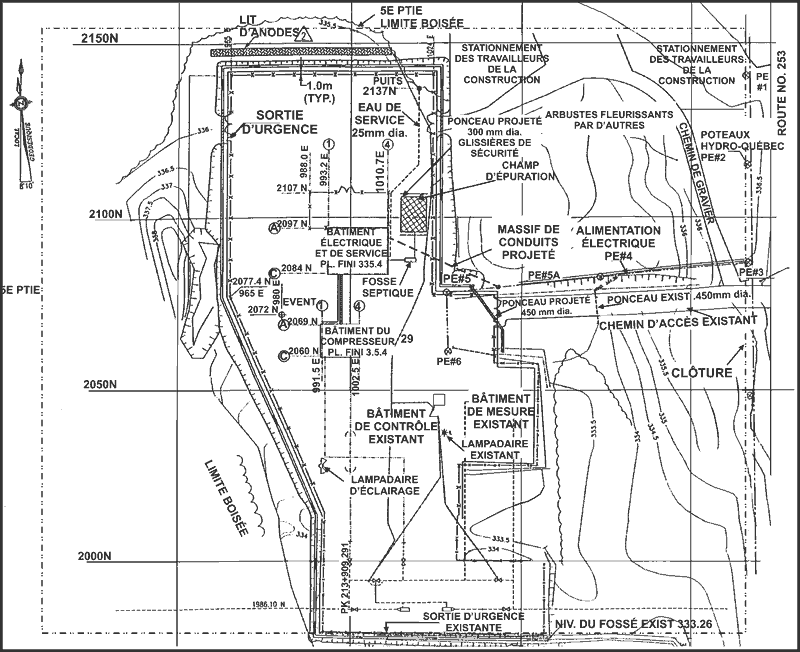
Appendix C - Schematic of the MOPICO unit and associated assembly of piping for the compressor
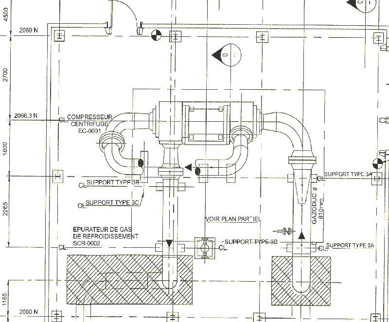
Appendix D - Schematic of station piping, valves and associated equipment

Appendix E - Bottom plate fitting for the terminal junction box (Scale: 1 to 2)

Appendix F - Table of physical measurements and physical conditions of the O-rings
| Original O-rings |
Weight (grams) | Width (mm) | Height (mm) | Measured density after test | Calculated density from data | Internal diameter (+/-0.3mm) |
Comments | |||||
|---|---|---|---|---|---|---|---|---|---|---|---|---|
| Avg | Gain after test | Avg | +/- min/max |
Avg after test | Avg | +/- min/max |
Avg after test | |||||
| U1-BB | 0.928 | 0.015 | 2.920 | 0.040 | 2.930 | 2.895 | 0.085 | 2.870 | 1.120 | 1.12 | 34.59 | Very, very soft. Faintly visible edge. |
| U2-BB | 0.952 | 0.025 | 2.890 | 0.011 | 2.800 | 2.910 | 0.060 | 2.830 | 1.216 | 1.229 | 34.59 | Very, very soft. No visible edge. |
| V1-BB | 0.923 | 0.017 | 2.930 | 0.060 | 2.810 | 2.755 | 0.055 | 2.900 | 1.020 | 1.049 | 31.42 | Very soft. Very faint edge visible. |
| U1-MO | 1.466 | 0.003 | 2.845 | 0.035 | 2.855 | 2.785 | 0.115 | 2.845 | 1.869 | 1.724 | 32.99 | Soft. No visible edge. |
| U2-MO | 1.440 | 0.005 | 2.840 | 0.010 | 2.785 | 2.750 | 0.020 | 2.700 | 1.829 | 1.830 | 32.99 | Very soft. Very faint edge visible. |
| V1-MO | 1.457 | 0.003 | 2.765 | 0.035 | 2.805 | 2.700 | 0.050 | 2.765 | 2.334 | 1.794 | 32.99 | Soft. Edge visible on one part of ring. |
| U3-BB | 0.803 | 0.015 | 2.615 | 0.035 | 2.715 | 2.510 | 0.060 | 2.755 | 1.150 | 1.041 | 32.99 | Soft. Sharp edge. |
| U3-MO | 0.752 | 0.055 | 2.585 | 0.045 | 2.710 | 2.455 | 0.055 | 2.795 | 1.147 | 1.013 | 32.99 | Soft. Sharp edge, no twisting. |
| W1-MO | 0.718 | 0.057 | 2.520 | 0.020 | 2.510 | 2.310 | 0.050 | 2.660 | 1.166 | 1.100 | 32.99 | Very stiff. Sharp edge. |
| V2-MO | 0.711 | 0.045 | 2.585 | 0.055 | 2.575 | 2.380 | 0.070 | 2.595 | 1.278 | 1.074 | 32.99 | Very stiff. Hard edge all around. |
| U4-BB | 0.763 | 0.042 | 2.610 | 0.040 | 2.770 | 2.500 | 0.050 | 2.780 | 1.090 | 0.996 | 32.99 | Stiff. Sharp edge. |
| U4-MO | 0.738 | 0.060 | 2.555 | 0.055 | 2.635 | 2.415 | 0.055 | 2.730 | 1.143 | 1.054 | 32.99 | Stiff. Sharp edge. |
| W3-BB | 0.743 | 0.064 | 2.665 | 0.055 | 2.570 | 2.360 | 0.040 | 2.735 | 1.163 | 1.089 | 32.99 | Very stiff. Prominent edge. |
| W3-MO | 0.743 | 0.077 | 2.620 | 0.030 | 2.615 | 2.410 | 0.050 | 2.740 | 1.172 | 1.087 | 32.99 | Stiff. Smooth edge. |
| W4-BB | 0.760 | 0.053 | 2.610 | 0.100 | 2.645 | 2.475 | 0.105 | 2.755 | 1.304 | 1.060 | 32.99 | Stiff. Piece of edge missing. |
| W4-MO | 0.735 | 0.112 | 2.570 | 0.020 | 2.710 | 2.435 | 0.045 | 2.735 | 1.108 | 1.087 | 32.99 | Very stiff. No twist. |
| V3-MO | 0.746 | 0.056 | 2.650 | 0.020 | 2.510 | 2.510 | 0.040 | 2.630 | 2.241 | 1.099 | 31.42 | Very stiff. Not in circular shape. Edge very rounded, barely distin- guishable. |
| W2-MO | 0.729 | 0.055 | 2.580 | 0.020 | 2.560 | 2.330 | 0.030 | 2.710 | 1.718 | 1.072 | 32.99 | Stiff. No twisting. |
| V2-BB | 0.795 | 0.045 | 2.810 | 0.020 | 2.720 | 2.620 | 0.080 | 2.850 | 1.161 | 1.031 | 32.99 | No twisting. Very round. Slight edge all around. |
| V3-BB | 0.794 | 0.051 | 2.640 | 0.060 | 2.660 | 2.595 | 0.025 | 2.680 | 1.316 | 1.127 | 32.99 | Very sharp edge on half side; other is very rounded. |
| V4-MO | 0.757 | 0.054 | 2.670 | 0.040 | 2.595 | 2.550 | 0.080 | 2.705 | 1.120 | 1.097 | 32.99 | Edge is apparent on one side, but is very smooth on the other. |
| W1-BB | 0.790 | 0.052 | 2.615 | 0.035 | 2.665 | 2.470 | 0.100 | 2.785 | 1.225 | 1.078 | 32.99 | Edge very rounded, somewhat soft. |
| W2-BB | 0.787 | 0.055 | 2.610 | 0.040 | 2.600 | 2.510 | 0.100 | 2.805 | 1.057 | 1.095 | 32.99 | Soft. Edge barely visible. |
| V4-BB | 0.738 | 0.058 | 2.735 | 0.125 | 2.745 | 2.600 | 0.090 | 2.680 | 1.115 | 0.983 | 31.42 | Slightly twisted around half the circum- ference. No surface marring. |
| Ref | 1.458 | N/A | 2.950 | 0.000 | N/A | 2.850 | 0.000 | N/A | 1.940 | 1.655 | 32.990 | New O-ring to be used as reference; never tested. |
| New | 1.447 | N/A | 2.879 | 0.066 | N/A | 2.855 | 0.054 | N/A | 1.845 | 1.679 | 32.99 | Good condition. |
| (New O-ringsused for test and measured afterward (U1-MO, V3-BB, W1-MO, W2-MO, and W3-NO). Result=average of these 5 O-rings) |
||||||||||||
| U3-BB | 1.445 | N/A | 2.875 | 0.045 | N/A | 2.880 | 0.020 | N/A | 2.824 | 1.665 | 32.99 | Slightly softer than reference. |
| W2-BB | 1.469 | N/A | 2.850 | 0.020 | N/A | 2.865 | 0.035 | N/A | 2.456 | 1.715 | 32.99 | Good condition. |
(Two other new O-ringsused for test and measured afterward)
= Out of tolerance compared with other similar O-rings
Appendix G - Reconstructed time line of events for the compressor station log
| Heure (TQM) | Événement (TQM) | Source d'information (TQM) | Time (TCPL) |
Event (TCPL) |
|---|---|---|---|---|
| 0604:32 | COMPRESSEUR E.H. BAT. COMPRESSEUR BAS DÉBIT CIRCULATION AIR | SCADA-ON | 0602:51 | Compr. bldg circ. air low flow alm |
| 1005 | ||||
| 1005:16 | COMPRESSEUR E.H. ÉVENT URGENCE (AUTOMATIQUE) |
SCADA-ON | 1003:51 | Automatic Unit #1 EBD alm |
| 1005:06 | COMPRESSEUR E.H. ARRKT URGENCE DU POSTE (MANUEL) | SCADA-ON | 1003:51 | Manual (PB button station) Unit #1 EBD |
| 1005:06 | COMPRESSEUR E.H. ÉVENT URGENCE (MANUEL) |
SCADA-ON | 1003:51 | Manual (PB station) station ESD alm |
| 1005:06 | COMPRESSEUR E.H. ALARME REGROUPÉE DU DÉCLENCHEMENT DU VFD | SCADA-ON | 1003:51 | Unit #1 VFD common trip |
| 1005:16 | COMPRESSEUR E.H. COUPURE DISJONCTEUR TRAFO (52-2) | SCADA-ON | 1003:51 | 25 kV swgr. pwr Xfmr brkr 52-2 trip alm |
| 1003:51 | 25 kV swgr. pwr Xfmr brkr 52-2 open alm | |||
| 1003:51 | A1 not running and loaded | |||
| 1005:16 (0604) | COMPRESSEUR E.H. BAT. COMPRESSEUR BAS DÉBIT CIRCULATION AIR | SCADA-OFF | ||
| 1005:36 | COMPRESSEUR E.H. HAUTE CONSIGNE PRESSION ASPIRATION | SCADA-ON | 1003:51 | pslowlimsp.pslowlimpv alm |
| 1004:12 | Unit #1 recycle valve not closed | |||
| 1004:12 | Unit #1 magnetic brg. rdy to rotate | |||
| 1004:12 | Stn disch. blwdn valve not closed | |||
| 1004:12 | Stn disch. isol. valve closed | |||
| 1004:12 | Stn suct. isol. valve closed | |||
| 1004:12 | Unit #1 discharge valve closed | |||
| 1004:12 | Unit #1 suction valve closed | |||
| 1004:12 | Unit #1 vent valve not closed | |||
| 1004:30 | Fail to seq. stn disch. isol. valve alm | |||
| 1004:30 | Fail to sequence Unit #1 disch. valve alm | |||
| 1006 | ||||
| 1006:46 | Unit #1 vent valve closed | |||
| 1015 | ||||
| 1014 | ||||
| 1035 | ||||
| 1106 | ||||
| 1110 | ||||
| 1115 | ||||
| 1120 | ||||
| 1217 | ||||
| 1219:37 | COMP. East Hereford TECHNICIEN SUR PLACE | SCADA-ON | 1217:48 | Security system disarmed (stn att) |
| 1220:56 (1005) | COMPRESSEUR E.H. ARRKT URGENCE DU POSTE (MANUEL) | SCADA-OFF | ||
| 1221:27 | COMPRESSEUR E.H. ARRKT URGENCE DU POSTE (MANUEL) | SCADA-ON | 1219:46 | Manual (PB station) station ESD alm |
| 1221:47 | COMPRESSEUR E.H. BAT. COMPRESSEUR BAS DÉBIT CIRCULATION AIR | SCADA-ON | 1220:07 | Compr. bldg circ. air low flow alm |
| 1221:47 (1005) | COMPRESSEUR E.H. ÉVENT URGENCE (MANUEL) | SCADA-OFF | ||
| 1221:47 (1005) | COMPRESSEUR E.H. ÉVENT URGENCE (AUTOMATIQUE) | SCADA-OFF | ||
| 1221:47 (1221) | COMPRESSEUR E.H. ARRKT URGENCE DU POSTE (MANUEL) | SCADA-OFF | ||
| 1222:57 (1005) | COMPRESSEUR E.H. COUPURE DISJONCTEUR TRAFO (52-2) | SCADA-OFF | ||
| 1222:57 (1005) | COMPRESSEUR E.H. ALARME REGROUPÉE DU DÉCLENCHEMENT DU VFD | SCADA-OFF | ||
| 1223:47 | COMPRESSEUR E.H. ARRKT A PARTIR DU PANNEAU DE CONTRÔLE | SCADA-ON | 1222:32 | A1 local control panel stop |
| 1223:47 | COMPRESSEUR E.H. COMMUTATEUR DE CONTRÔLE EN MODE LOCAL | SCADA-ON | 1222:32 | Crtl panel loc/remote switch in local |
| 1223:47 | COMPRESSEUR E.-H. COMMUTATEUR DE CONTRÔLE EN MODE ASSISTANCE | SCADA-OFF | ||
| 1222:32 | 25 kV swgr pwr Xfmr brk 52-2 not open | |||
| 1223:57 (1223) | COMPRESSEUR E.H. ARRKT A PARTIR DU PANNEAU DE CONTRÔLE | SCADA-OFF | ||
| 1224:57 (1221) | COMPRESSEUR E.H. BAT. COMPRESSEUR BAS DÉBIT CIRCULATION AIR | SCADA-OFF | ||
| 1225:37 | COMPRESSEUR E.H. SYSTOME DE SÉCURITÉ CONTOURNÉ POUR 1 HEURE | SCADA-ON | 1224:05 | Safety systems bypass timer alm |
| 1246:42 | COMPRESSEUR E.H. ARRKT A PARTIR DU PANNEAU DE CONTRÔLE | SCADA-ON | 1234:46 | A1 local control panel start |
| 1246:53 (1246) | COMPRESSEUR E.H. ARRKT A PARTIR DU PANNEAU DE CONTRÔLE | SCADA-OFF | ||
| 1241:19 | Fail to seq. stn discharge blowdown | |||
| 1252:13 | COMPRESSEUR E.H. ÉVENT URGENCE (AUTOMATIQUE) | SCADA-ON | 1250:48 | Automatic Unit #1 EBD alm |
| 1252:13 | COMPRESSEUR E.H. ÉVENT URGENCE (MANUEL) | SCADA-ON | 1250:48 | Manual (PB station) Unit #1 EBD |
| 1252:13 | COMPRESSEUR E.H. BASSE TEMPÉRATURE MINIMUM ENROULEMENT MOTEUR | SCADA-ON | ||
| 1252:13 | COMPRESSEUR E.H. BASSE TEMPÉRATURE MOYENNE ENROULEMENT MOTEUR | SCADA-ON | ||
| 1252:13 | COMPRESSEUR E.H. ALARME REGROUPÉE DU DÉCLENCHEMENT DU VFD | SCADA-ON | 1250:48 | Unit #1 VFD common trip alm |
| 1252:13 | COMPRESSEUR E.H. COUPURE DISJONCTEUR TRAFO (52-2) | SCADA-ON | 1250:48 | 25 kV swgr pwr Xfmr brkr 52-2 trip alm |
| 1251:09 | 25 kV swgr pwr Xfmr brkr 52-2 open alm | |||
| 1252:23 (1252) | COMPRESSEUR E.H. ÉVENT URGENCE (AUTOMATIQUE) | SCADA-OFF | ||
| 1252:33 | COMPRESSEUR E.H. ÉVENT URGENCE (AUTOMATIQUE) | SCADA-ON | ||
| 1252:43 (1252) | COMPRESSEUR E.H. ÉVENT URGENCE (AUTOMATIQUE) | SCADA-OFF | ||
| 1258:43 | COMPRESSEUR E.H. PERTE TENSION DISJ. MOTEUR | SCADA-ON | ||
| 1258:53 (1258) | COMPRESSEUR E.H. PERTE TENSION DISJ. MOTEUR | SCADA-OFF | ||
| 1259:03 | COMPRESSEUR E.H. ÉVENT URGENCE (AUTOMATIQUE) | SCADA-ON | 1257:44 | Automatic Unit #1 EBD alm |
| 1259:03 | COMPRESSEUR E.H. ARRKT URGENCE DU POSTE (MANUEL) | SCADA-ON | 1257:44 | Manual (PB station) station ESD alm |
| 1259:03 | COMPRESSEUR E.H. BASSE PRESSION GAZ DE SERVICE (2 800 kPa) | SCADA-ON | 1257:44 | Power gas low-pressure alm |
| 1259:33 (1225) | COMPRESSEUR E.H. SYSTOME DE SÉCURITÉ CONTOURNÉ POUR 1 HEURE | SCADA-OFF | ||
| 1259:43 | COMPRESSEUR E.H. ÉVENT URGENCE (AUTOMATIQUE) | SCADA-ON | 1258:18 | Automatic Unit #1 EBD alm |
| 1259:33 (1259) | COMPRESSEUR E.H. ÉVENT URGENCE (AUTOMATIQUE) | SCADA-OFF | ||
| 1259:53 | COMPRESSEUR E.H. COMMUTATEUR DE CONTRÔLE EN MODE MANUEL | SCADA-ON | 1258:19 | A1 manual |
| 1300 | ||||
| 1300:03 (1259) | COMPRESSEUR E.H. ARRKT URGENCE DU POSTE (MANUEL) | SCADA-OFF | ||
| 1300:03 (1259) | COMPRESSEUR E.H. BASSE PRESSION GAZ DE SERVICE (2 800 kPa) | SCADA-OFF | ||
| 1300:13 | COMPRESSEUR E.H. BAT. COMPRESSEUR BAS DÉBIT CIRCULATION AIR | SCADA-ON | 1258:36 | Comp. bldg circ. air low flow alm |
| 1306:13 | COMPRESSEUR E.H. ÉVENT URGENCE (AUTOMATIQUE) | SCADA-ON | 1304:30 | Automatic Unit #1 EBD alm |
| 1306:13 | COMPRESSEUR E.H. ARRKT URGENCE DU POSTE (MANUEL) | SCADA-ON | 1304:30 | Manual (PB station) station ESD alm |
| 1306:13 (1259) | COMPRESSEUR E.H. COMMUTATEUR DE CONTRÔLE EN MODE MANUEL | SCADA-OFF | ||
| 1306:13 (1300) | COMPRESSEUR E.H. BAT. COMPRESSEUR BAS DÉBIT CIRCULATION AIR | SCADA-OFF | ||
| COMPRESSEUR E.H. ÉVENT URGENCE (MANUEL) | SCADA-OFF | |||
| 1306:43 | COMPRESSEUR E.H. BAT. COMPRESSEUR BAS DÉBIT CIRCULATION AIR | SCADA-ON | 1305:19 | Comp. bldg circ. air low flow alm |
| 1306:43 (1306) | COMPRESSEUR E.H. ÉVENT URGENCE (AUTOMATIQUE) | SCADA-OFF | ||
| 1312:48 | Main line valve not closed | |||
| 1313 | ||||
| 1326:28 | Stn. disch. blwdn valve closed | |||
| 1327:07 | Fail to seq. stn disch. blwdn valve alm | |||
| 1328:19 | Stn disch. blwdn valve not closed | |||
| 1331:53 | Stn disch. blwdn valve closed | |||
| 1335:17 | COMPRESSEUR E.H. ÉVENT URGENCE (MANUEL) | SCADA-ON | 1333:26 | Manual (PB station) Unit #1 EBD |
| 1335:37 | COMPRESSEUR E.H. ÉVENT URGENCE (AUTOMATIQUE) | SCADA-ON | 1333:44 | Automatic Unit #1 EBD alm |
| 1335:47 (1335) | COMPRESSEUR E.H. ÉVENT URGENCE (AUTOMATIQUE) | SCADA-OFF | ||
| 1335:57 (1335) | COMPRESSEUR E.H. ÉVENT URGENCE (MANUEL) | SCADA-OFF | ||
| 1336:17 (1252) | COMPRESSEUR E.H. ALARME REGROUPÉE DU DÉCLENCHEMENT DU VFD | SCADA-OFF | ||
| COMPRESSEUR E.H. COUPURE DISJONCTEUR TRAFO (52-2) | SCADA-OFF | 1335:19 | 25 kV swgr pwr Xfmr brkr 52-2 not open | |
| 1348:10 | Automatic Unit #1 EBD alm | |||
| 1340:48 (1259) | COMPRESSEUR E.H. BASSE PRESSION GAZ DE SERVICE (2 800 kPa) |
SCADA-OFF | ||
| 1342 | ||||
| 1349:49 | COMPRESSEUR E.H. ÉVENT URGENCE (MANUEL) | SCADA-ON | 1348:10 | Manual (PB station) Unit #1 EBD |
| 1349:49 | COMPRESSEUR E.H. ARRKT URGENCE DU POSTE (MANUEL) | SCADA-ON | 1348:10 | Manual (PB station) station ESD alm |
| 1349:49 | COMPRESSEUR E.H. ÉVENT URGENCE (AUTOMATIQUE) | SCADA-ON | ||
| 1348:10 | Power gas low-pressure alm | |||
| 1349:49 | COMPRESSEUR E.H. ALARME REGROUPÉE DU DÉCLENCHEMENT DU VFD | SCADA-ON | 1348:10 | Unit #1 VFD common trip alm |
| 1349:49 | COMPRESSEUR E.H. COUPURE DISJONCTEUR TRAFO (52-2) | SCADA-ON | 1348:10 | 25 kV swgr pwr Xfmr brkr 52-2 trip alm |
| 1349:49 (1305) | COMPRESSEUR E.H. BAT. COMPRESSEUR BAS DÉBIT CIRCULATION AIR | SCADA-OFF | ||
| 1350:09 (1349) | COMPRESSEUR E.H. ARRKT URGENCE DU POSTE (MANUEL) | SCADA-OFF | ||
| 1348:10 | 25 kV swgr pwr Xfmr brkr 52-2 open alm | |||
| 1350:19 | COMPRESSEUR E.H. BAT. COMPRESSEUR BAS DÉBIT CIRCULATION AIR | SCADA-ON | 1348:29 | Compr. bldg circ. air low flow alm |
| 1350:29 | COMPRESSEUR E.H. ÉVENT URGENCE (MANUEL) | SCADA-ON | 1348:47 | Manual (PB station) Unit #1 EBD |
| 1350:59 (1349) | COMPRESSEUR E.H. ÉVENT URGENCE DU POSTE (AUTOMATIQUE) | SCADA-OFF | ||
| 1351:29 (1350) | COMPRESSEUR E.H. ÉVENT URGENCE (MANUEL) | SCADA-OFF | ||
| 1353:49 | COMPRESSEUR E.H. ÉVENT URGENCE (AUTOMATIQUE) | SCADA-ON | 1352:14 | Automatic Unit #1 EBD alm |
| 1353:49 | COMPRESSEUR E.H. ÉVENT URGENCE (MANUEL) | SCADA-ON | 1352:14 | Manual (PB station) Unit #1 EBD |
| 1353:59 (1353) | COMPRESSEUR E.H. ÉVENT URGENCE (AUTOMATIQUE) | SCADA-OFF | ||
| 1425:54 (1353) | COMPRESSEUR E.H. ÉVENT URGENCE (MANUEL) | SCADA-OFF | ||
| 1442 | ||||
| 1445:38 | Stn suct. purge/press valve not closed | |||
| 1445:38 | Unit #1 purge/press valve not closed | |||
| 1445:38 | Unit #1 vent valve not closed | |||
| 1446 | ||||
| 1447:28 | COMPRESSEUR E.H. HAUTE PRESSION J.B. DU MOTEUR | SCADA-ON | 1446:02 | Unit #1 motor JB high-pressure alm |
| 1447:28 | COMPRESSEUR E.H. ARRKT URGENCE SANS ÉVENT (AUTOMATIQUE) | SCADA-ON | 1446:02 | Automatic Unit #1 ESD alm |
| 1448 | 1447:57 | Unit #1 recycle valve closed | ||
| 1447:58 | A1 recycle valve open alm | |||
| 1450:10 (1349) | COMPRESSEUR E.-H. ALARME REGROUPÉE DU DÉCLENCHEMENT DU VFD | SCADA-OFF | ||
| 1450:50 (1349) | COMPRESSEUR E.H. COUPURE DISJONCTEUR TRAFO (52-2) | SCADA-OFF | 1449:40 | 25 kV swgr pwr Xfmr brkr 52-2 not open |
| 1450 | ||||
| 1450 | ||||
| 1452:11 (1350) | COMPRESSEUR E.H. BAT. COMPRESSEUR BAS DÉBIT CIRCULATION AIR | SCADA-OFF | ||
| 1452 | ||||
| 1451:09 | Unit#1 recycle valve not closed | |||
| 1451:09 | A1 local control panel stop | |||
| 1451:29 | Stn suct. isol. valve not closed | |||
| 1452:05 | Stn suct. purge/press valve closed | |||
| 1454:34 | Main line valve closed | |||
| 1454:34 | Stn disch. isol. valve not closed | |||
| 1454 | ||||
| 1455:11 | COMPRESSEUR E.H. BASSE CONSIGNE PRESSION DE SORTIE | SCADA-ON | ||
| 1455:11 (1005) | COMPRESSEUR E.H. HAUTE CONSIGNE PRESSION ASPIRATION | SCADA-OFF | ||
| 1455 | ||||
| 1456 | ||||
| 1456:07 | 25 kV swgr pwr Xfmr brkr 52-2 open alm | |||
| 1457 | ||||
| 1458 | ||||
| 1500:44 | Unit #1 vent valve closed | |||
| 1501:41 | Unit #1 suction valve not closed | |||
| 1504:02 | Unit #1 vent valve not closed | |||
| 1505:32 | Unit #1 vent valve closed | |||
| 1518 | ||||
| 1518 | ||||
| 1529 | ||||
| 1531:45 | COMPRESSEUR E.H. ALARME REGROUPÉE DU DÉCLENCHEMENT DU VFD | SCADA-ON | 1530:20 | Unit #1 VFD common trip alm |
| 1531:45 | COMPRESSEUR E.H. ÉVENT URGENCE (MANUEL) | SCADA-ON | 1530:20 | Manual (PB station) Unit #1 EBD |
| 1531:45 | COMPRESSEUR E.H. COUPURE DISJONCTEUR TRAFO (52-2) | SCADA-ON | 1530:20 | 25 kV swgr pwr Xfmr brkr 52-2 trip alm |
| 1531 | ||||
| 1530:54 | Unit #1 suction valve closed | |||
| 1530:54 | Unit #1 vent valve not closed | |||
| 1531:17 | Fail to sequence Unit #1 disch. valve alm | |||
| 1531:17 | Fail to seq. Unit #1 suct. valve alm | |||
| 1532:06 | Fail to sequence Unit #1 disch. valve alm | |||
| 1532:06 | Fail to seq. Unit #1 suct. valve alm | |||
| 1533:26 | COMPRESSEUR E.H. DISJONCTEUR PRINCIPAL (52-1) OUVERT | SCADA-ON | ||
| 1533:36 (1533) | COMPRESSEUR E.H. DISJONCTEUR PRINCIPAL (52-1) OUVERT | SCADA-OFF | ||
| 1534:26 | COMPRESSEUR E.H. ÉVENT URGENCE (AUTOMATIQUE) | SCADA-ON | 1532:45 | Automatic Unit #1 EBD alm |
| 1534:26 | COMPRESSEUR E.H. ARRKT URGENCE DU POSTE (MANUEL) | SCADA-ON | 1532:45 | Manual (PB station) station ESD alm |
| 1534:36 (1531) | COMPRESSEUR E.H. ÉVENT URGENCE (MANUEL) | SCADA-OFF | ||
| 1534:36 (1534) | COMPRESSEUR E.H. ÉVENT URGENCE (AUTOMATIQUE) | SCADA-OFF | ||
| 1534:36 (1534) | COMPRESSEUR E.H. ARRKT URGENCE DU POSTE (MANUEL) | SCADA-OFF | ||
| 1534:56 | COMPRESSEUR E.H. BAT. COMPRESSEUR BAS DÉBIT CIRCULATION AIR | SCADA-ON | 1533:17 | Compr. bldg circ. air low flow alm |
| 1534 | ||||
| 1533:17 | Stn disch. isol. valve closed | |||
| 1533:17 | Stn suct. isol. valve closed | |||
| 1533:36 | Main line valve not closed | |||
| 1533:36 | Unit #1 suction valve not closed | |||
| 1534:14 | Fail to seq. stn disch. blwdn valve alm | |||
| 1542:32 | Fail to seq. stn disch. blwdn valve alm | |||
| 1542 | ||||
| 1546 | ||||
| 1546:30 | Stn disch. blwdn valve not closed | |||
| 1549:08 | COMPRESSEUR E.H. ÉVENT URGENCE (AUTOMATIQUE) | SCADA-ON | 1547:49 | Manual (PB station) Unit #1 EBD |
| 1549:08 | COMPRESSEUR E.H. HAUTE CONSIGNE PRESSION ASPIRATION | SCADA-ON | ||
| 1549:08 | COMPRESSEUR E.H. ÉVENT URGENCE (MANUEL) | SCADA-ON | ||
| 1549:08 (1455) | COMPRESSEUR E.H. BASSE CONSIGNE PRESSION DE SORTIE | SCADA-OFF | ||
| 1549:18 | COMPRESSEUR E.H. BASSE CONSIGNE PRESSION DE SORTIE | SCADA-ON | ||
| 1549:18 (1549) | COMPRESSEUR E.H. ÉVENT URGENCE (AUTOMATIQUE) | SCADA-OFF | ||
| 1549:18 (1549) | COMPRESSEUR E.H. HAUTE CONSIGNE PRESSION ASPIRATION | SCADA-OFF | ||
| 1549 | ||||
| 1548:08 | Unit #1 suction valve closed | |||
| 1548:42 | Fail to sequence Unit #1 disch. valve alm | |||
| 1548:42 | Fail to seq. Unit #1 suct. valve alm | |||
| 1550:46 | A1 local control panel stop | |||
| 1551:48 (1549) | COMPRESSEUR E.H. ÉVENT URGENCE (MANUEL) | SCADA-OFF | ||
| 1553:08 | COMPRESSEUR E.H. SYSTOME DE SÉCURITÉ CONTOURNÉ POUR 1 HEURE | SCADA-ON | 1551:37 | Safety systems bypass timer alm |
| 1551:37 | Stn disch. blwdn valve closed | |||
| 1551:37 | Stn disch. isol. valve not closed | |||
| 1551:37 | Stn suct. isol. valve not closed | |||
| 1551:37 | Unit #1 discharge valve not closed | |||
| 1551:37 | Unit #1 suction valve not closed | |||
| 1551:58 | Main line valve closed | |||
| 1600 | ||||
| 1601 | ||||
| 1601:15 | ||||
| 1601:49 | COMPRESSEUR E.H. ÉVENT URGENCE (MANUEL) | SCADA-ON | 1600:20 | Manual (PB station) Unit #1 EBD |
| 1601:56 | ||||
| 1602 | ||||
| 1602:09 (1549) | COMPRESSEUR E.H. BASSE CONSIGNE PRESSION DE SORTIE | SCADA-OFF | ||
| 1602:29 | COMPRESSEUR E.H. ÉVENT URGENCE (AUTOMATIQUE) | SCADA-ON | 1600:49 | Automatic Unit #1 EDB alm |
| 1602:29 | COMPRESSEUR E.H. ARRKT URGENCE DU POSTE (MANUEL) | SCADA-ON | 1600:49 | Manual (PB station) station ESD alm |
| 1600:49 | Unit #1 discharge valve closed | |||
| 1600:49 | Unit #1 suction valve closed | |||
| 1602:19 | COMPRESSEUR E.H. HAUTE CONSIGNE PRESSION ASPIRATION | SCADA-ON | 1600:49 | pslowlimsp>pslowlimpv alm |
| 1601:12 | Main line valve not closed | |||
| 1602:29 (1534) | COMPRESSEUR E.H. BAT. COMPRESSEUR BAS DÉBIT CIRCULATION AIR | SCADA-OFF | ||
| 1601:12 | Stn disch. blwdn valve not closed | |||
| 1601:12 | Stn disch. isol. valve closed | |||
| 1601:12 | Stn suct. isol. valve closed | |||
| 1602:34 | ||||
| 1602:59 | ||||
| 1603:19 (1447) | COMPRESSEUR E.H. HAUTE PRESSION J.B. DU MOTEUR | SCADA-OFF | 1601:31 | Fail to seq. stn disch. isol. valve alm |
| 1605 | ||||
| 1605:20 | COMPRESSEUR E.H. HAUTE PRESSION J.B. DU MOTEUR | SCADA-ON | 1605:35 | Unit #1 motor JB high-pressure alm |
| 1606:10 | COMPRESSEUR E.H. BASSE CONSIGNE PRESSION DE SORTIE | SCADA-ON | ||
| 1606:10 (1602) | COMPRESSEUR E.H. HAUTE CONSIGNE PRESSION ASPIRATION | SCADA-OFF | ||
| 1606 | ||||
| 1607 | ||||
| 1608:22 | pslowlimsp>pslowlimpv alm | |||
| 16h10 | ||||
| 1610:00 (1606) | COMPRESSEUR E.H. BASSE CONSIGNE PRESSION DE SORTIE | SCADA-OFF | ||
| 1613 | ||||
| 1616:32 (1605) | COMPRESSEUR E.H. HAUTE PRESSION J.B. DU MOTEUR | SCADA-OFF | ||
| 1617:06 | Unit #1 purge/press valve closed | |||
| 1628 | ||||
| 1642 | ||||
| 1645 | ||||
| 1655:07 (1553) | COMPRESSEUR E.H. SYSTOME DE SÉCURITÉ CONTOURNÉ POUR 1 HEURE | SCADA-OFF | ||
| 1700 | ||||
| 1705 | ||||
| 1715 | ||||
| 1718 | ||||
| 1720 | ||||
| 1721 | ||||
| 1723 | ||||
| 1724:41 | East Hereford DÉFAUT DE COMMUNICATION AVEC BRISTOL A | SCADA-ON | 1723:13 | Dedicated line comm. fail alm |
| 1726:51 | East Hereford DÉFAUT DE COMMUNICATION AVEC LIEN COMMUTE | SCADA-ON | ||
| 1732:58 | Data not updating alm |
Appendix H - Glossary
- Avrg
- average
- CEC
- Canadian Electrical Code
- CEC 22.1
- Canadian Electrical CodeC22.1, Safety Standards for Electrical Installations
- CSA
- Canadian Standards Association
- CSA Z662
- standard CAN/CSA-Z662 entitled Oil and Gas Pipeline Systems
- EBD
- emergency blowdown
- E.H.
- East Hereford
- ESB
- electrical and services building
- ESD
- emergency shutdown
- EUBD
- emergency unit blowdown
- GCC
- Gas Control Centre
- ISO
- International Organization for Standardization
- km
- kilometre
- km/h
- kilometre per hour
- KMP
- Kilometre Post
- kPa
- kilopascal
- kV
- kilovolt
- LEL
- lower explosive limit
- m
- metre
- m³
- cubic metre
- mg/m³
- milligram per cubic metre
- MLBV
- Main Line Block Valve
- mm
- millimetre
- MOPICO
- motor pipeline compressor
- MW
- megawatt
- N/A
- not applicable
- NEB
- National Energy Board
- PNGS
- Portland Natural Gas System
- RBQ
- Régie du bâtiment du Québec
- SCADA
- Supervisory Control and Data Acquisition
- STOP
- normal stop
- TCPL
- TransCanada PipeLines Limited
- TIL
- technical information letter
- TJB
- terminal junction box
- TQM
- Gazoduc TQM Inc.
- TSB
- Transportation Safety Board of Canada
- UL
- Underwriters Laboratory Inc.
- UEL
- upper explosive limit
- U.S.
- United States of America
- VFD
- variable frequency drive
- ° C
- degree Celsius